1−4
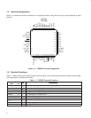
1.4 Terminal Assignments
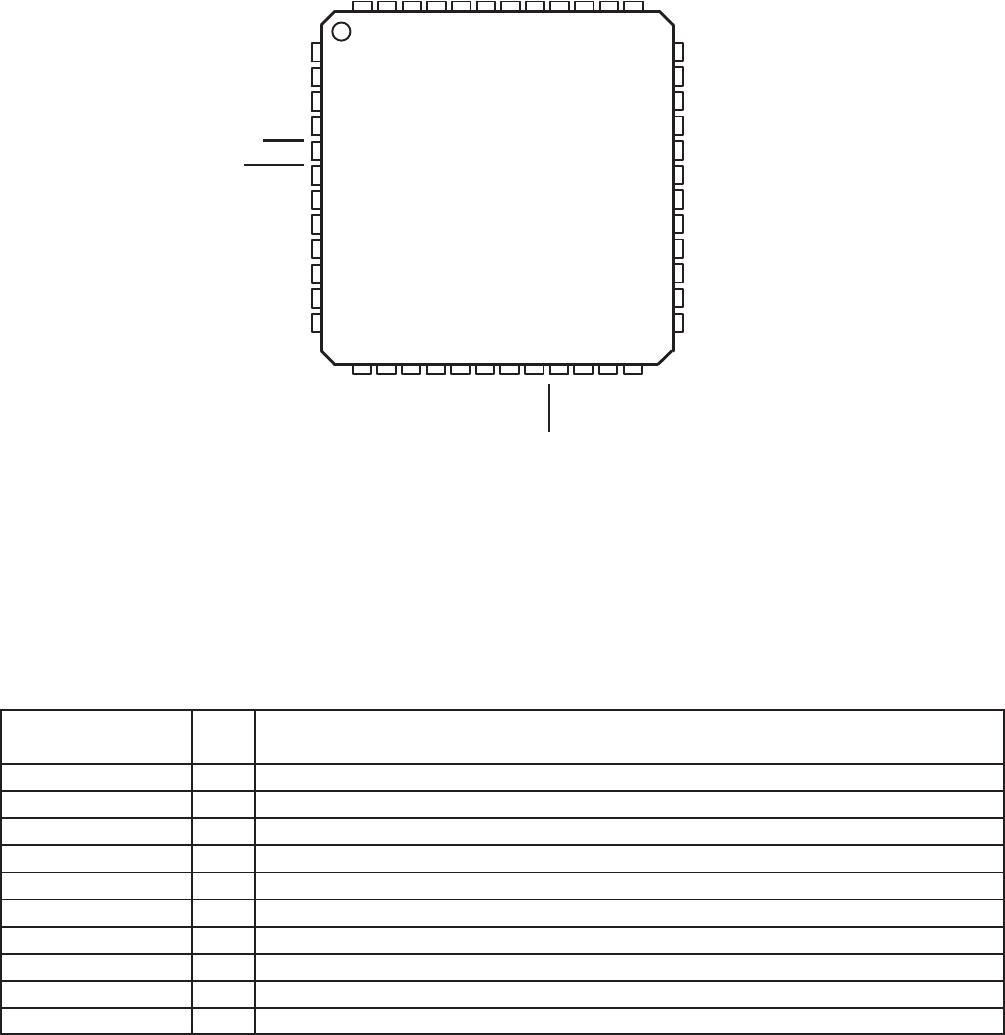
Figure 1−2 shows the terminal locations on the package outline, along with the signal name assigned to each
terminal.
14 15
NC
AV
DD
NC
GPI5
GPI4
GPI3
GPI2
GPI1
GPI0
ALLPASS
SDOUT1
SDOUT0
36
35
34
33
32
31
30
29
28
27
26
25
16
1
2
3
4
5
6
7
8
9
10
11
12
LINA
V
RFILT
AV
SS(REF)
AV
SS
INPA
RESET
CS1
PWR_DN
TEST
CAP_PLL
CLKSEL
MCLKO
17 18 19 20
AINRM
AINRP
AOUTR
VCOM
47 46 45 44 4348 42
LINB
AINLP
V
AINLM
40 39 3841
21
22 23 24
37
13
AOUTL
RINA
RINB
PACKAGE
(TOP VIEW)
XTALI/MCLK
XTALO
SCL
SDA
DV
DD
DV
SS
LRCLK/O
SCLK/O
IFM/S
SDIN1
SDIN2
SDOUT2
REFM
V
REFP
Figure 1−2. TAS3002 Terminal Assignments
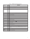
1.5 Terminal Functions
Table 1−1 lists the terminals in alphanumeric order by signal name, along with the terminal number, terminal type,
and a description of the terminal function.
Table 1−1. TAS3002 Terminal Functions
TERMINAL
I/O
DESCRIPTION
NAME NO.
I/O
DESCRIPTION
AINLM 46 I ADC left channel analog input (antialias capacitor)
AINLP 47 I ADC left channel analog input (antialias capacitor)
AINRM 43 I ADC right channel analog input (antialias capacitor)
AINRP 42 I ADC right channel analog input (antialias capacitor)
ALLPASS 27 I Logic high bypasses equalization filters
AOUTL 39 O Left channel analog output
AOUTR 37 O Right channel analog output
AV
DD
35 I Analog power supply (3.3 V)
AV
SS
4 I Analog voltage ground
AV
SS(REF)
3 I Analog ground voltage reference


