


2−2
2.2 Digital Output Modes
The digital output modes (SDOUT1, SDOUT2, SDOUT0) are described in Sections 2.2.1 through 2.2.3.
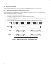
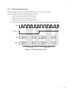
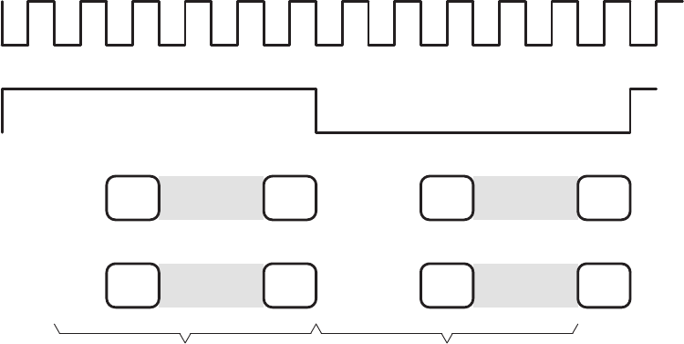
2.2.1 MSB-First, Right-Justified, Serial-Interface Format
The normal output mode for the MSB-first, right-justified, serial-interface format is for 16, 18, 20, or 24 bits. Figure 2−1
shows the following characteristics of this protocol:
• Left channel is transmitted when LRCLK is high.
• The SDIN(s) (recorded) data is justified to the trailing edge of the LRCLK.
• The SDOUT(s) MSB (playback) data is transmitted at the same time as LRCLK edge and captured at the
next rising edge of SCLK.
• If the LRCLK phase changes by more than 10 cycles ofMCLK, the codec automatically resets.
SCLK
LRCLK = f
S
MSB LSB
………… ……
MSB LSB
……
SDIN
MSB LSB
…… ……
MSB LSB
……
Left Channel Right Channel
SDOUT
……
Figure 2−1. MSB-First, Right-Justified, Serial-Interface Format