


8−2
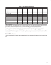
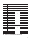
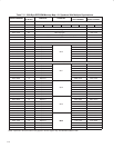
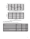
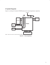
8.4 ADC Digital Filter
T
A
= 25°C, AV
DD
= 3.3 V, DV
DD
= 3.3 V, f
S
= 48 kHz, 20-bit I
2
S mode
All terms characterized by frequency are scaled with the chosen sampling frequency, f
S
. See Figure 8−1 through
Figure 8−4 for performance curves of the ADC digital filter.
PARAMETER TEST CONDITIONS MIN TYP MAX UNIT
ADC decimation filter (LPF)
Pass band 0.0 20.0 kHz
ADC decimation filter (LPF)
Pass band ripple ±0.01 dB
Stop band 24.1 kHz
Stop band attenuation 80 dB
Group delay 720 µs
ADC high-pass filter (HPF)
Pass band (−3 dB) 0.87 Hz
ADC high-pass filter (HPF)
Deviation from linear phase 20 Hz to 20 kHz 1.23 degrees
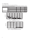
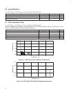
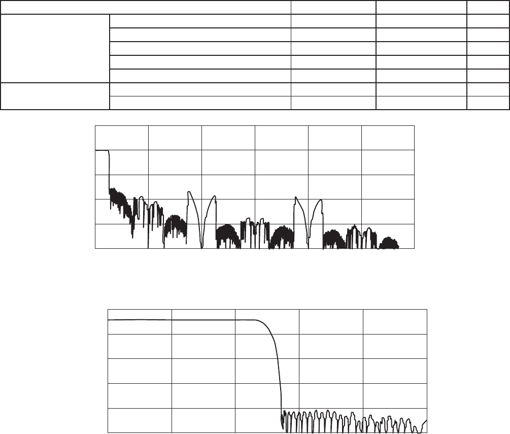
−150
−200
Amplitude − dB
−50
0
50
−100
f − Frequency − Hz
02 f
s
4 f
s
6 f
s
8 f
s
10 f
s
12 f
s
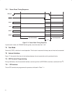
Figure 8−1. ADC Digital Filter Characteristics
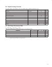
−60
−100
Amplitude − dB
−40
−20
0
−80
0
f − Frequency − Hz
0.2 f
s
0.4 f
s
0.6 f
s
0.8 f
s
1 f
s
Figure 8−2. ADC Digital Filter Stop-Band Characteristics