


ELECTRO-VOICE
®
6
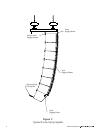
The grid is suspended by two hoist motors that are attached to two pickup points on the top of the
grid one at the front and one at the back. The two grid pickup points are in line and are
adjustable front to back to help distribute the loads between the hoist motors. For smaller arrays
(8 boxes or less), two one-ton hoist motors are recommended. For larger arrays (more than 8
boxes), two two-ton hoist motors are recommended. Two one-ton hoist motors can be used;
however, the front-to-back distribution of the weight becomes much more critical than with two-ton
hoists.
Note that the weight of an array can be quite substantial and the grid, chain
hoists and building structural supports used to suspend the array must be
capable of supporting such a load with a sufficient safety factor. The reader is
directed to References section of this manual for a list of rigging references (for
background in general rigging practice) and mechanical engineering references
(for background in structural engineering analysis).
1.2 Enclosure Rigging Hardware Details
The X-Line loudspeaker systems have rigging at both the front and rear of the enclosures. The
Xvls, Xvlt and Xsub systems all have the same rigging hardware on both the front and rear of the
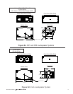
enclosures. While the Xfil1 and Xfil2 use the same rigging as the others on the rear of the
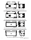
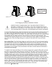
enclosures, they use different rigging at the front. Figure 2 shows key dimensions, weights and
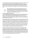
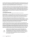
centers of gravity for all of the X-Line loudspeaker systems. Figure 3 shows the enclosure rigging
hardware details and key dimensions.
A proprietary high-strength aluminum-alloy track is used at the rear of the enclosures near the top
and bottom for the attachment of two Xvhg rigging hinges, two Xvhl rigging hinges, two Xvhp pick-
up hinges, or one Xvbp pull-up bar. The track/bracket assembly is extruded as a single piece. One
assembly ties into the back and top of the enclosure, while a second assembly ties into the back
and bottom of the enclosure. Four high-strength, aluminum-alloy bars inside the enclosure tie the
top and bottom track/bracket assemblies together, minimizing the load applied to the enclosure
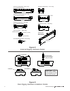
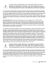
shell. The cutouts in the rear rigging track are shown in Figure 3a and 3b. The large cutout at the
end of the track is for inserting the rigging hinges. The small holes in the base of the track are for
locking the rigging hinges. The round cutouts are provided so two Electro-Voice RS-1B double-
stud swivel-ring fittings may be installed for light-duty lifting applications and for pull-ups. (The
track is also compatible with the New Haven NH32102-2 double-stud fittings.)
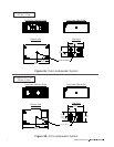
At the front of the Xvls, Xvlt and Xsub enclosures is another pair of proprietary high-strength,
aluminum-alloy track/bracket assemblies, which are also extruded as a single piece. One
assembly ties into the left side, top, bottom of the enclosure, while a second assembly ties into the
right side, top and bottom of the enclosure. The front track extends from the top to the bottom on
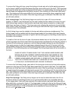
both sides of the enclosure, eliminating the load applied to the enclosure shell. On both sides of
the enclosure, the front rigging track has six cutouts near the top and bottom, as shown in Figure
3c. The triple-stud fittings on the Xvsg and Xvsl chain rigging straps may be installed at any of the
cutouts. The relative angle between a pair of enclosures (or the top enclosure and the grid) is set
by the position of the front rigging-strap fittings in the track cutouts.