


ELECTRO-VOICE
®
16
Xvsf Rigging Fitting: Two Xvsf rigging fittings can be used to attach the front of an X-Line
enclosure directly to a building structure or to a grid assembly that is not compatible with the
X-Line rigging track. The fitting is a proprietary triple-stud fitting that has a large steel locating
plunger. The plunger not only locates in the round cutouts in the track, but also extends into the
base of the track for extra strength. A 3/8-inch shackle can be attached to the end of the chain.
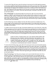
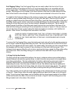
To install the Xvsf triple-stud fittings in the enclosure rigging track, grasp the fitting with one hand
and pull the spring-loaded safety locking pin out with your free hand. Continue to pull until the
locking pin retracts above the three stud feet of the fitting. Insert the three round feet on the end of
the fitting into the round cutouts in the track and slide the fitting to the desired position. Center the
locking pin of the fitting over one of the track cutouts. Release the locking pin. The pin should
extend beyond the bottom of the fitting and should lock into the round recess in the base of the
track with the locking pin retracting to its normal position as shown in Figure 6. If the pin does not
lock into the base of track, nudge it along the track and wiggle as necessary until it settles into
position. When locked, the fitting will be immovable in the track.
ALWAYS CHECK TO MAKE SURE THAT THE FITTING IS SECURELY LOCKED
INTO THE TRACK, AND THAT THE LOCKING PIN IS FULLY SEATED INTO THE
BASE OF THE TRACK BEFORE LIFTING ANY LOUDSPEAKER ENCLOSURE
OVERHEAD.
To remove the Xvsf rigging fitting, grasp the locking-pin knob and pull out while applying pressure
on the hinge to slide the hinge base along the track. The three stud feet will come out of the track
once they are aligned with the track cutouts. For added safety, the locking pin has a special shape
that engages with the track to prevent it from vibrating out of the track hole during use. If the
locking-pin knob seems difficult to pull out when removing the hinge, wiggle the fitting while pulling
out on the knob. When the fitting locking pin is centered in the track hole, the pin will easily
release.
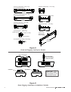
1.5 Xvbp Pull-Up Bar Details
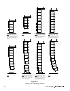
The Xvbp pull-up bar is used at the bottom of an array in instances where more vertical splay is
needed between cabinets than gravity allows, or when the entire array needs to be angled down
more than gravity allows. The bar is attached to the bottom cabinet of an array and a nylon or
polyester ratchet strap is connected between the center eye ring of the Xvbp and the grid
suspending the array. Once the array is floated in the air, the ratchet strap may be tightened to
remove the slack from the front linking straps and achieve the desired splay angles. The ratchet
strap will be provided by the user and must have a working-load rating of 2000 pounds (907 kg).
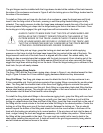
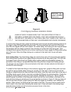
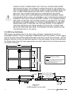
The Xvbp consists of a bar with two hinge base fittings at the outside edges of the bar as shown
in Figure 4. These fittings utilize the same rigging attachment base that is used on the Xvhg grid
hinge. The pull-up-bar hinge bases must be installed with the hinge bases located at the outside
of the track towards the sides of the enclosure as shown in Figure 5 with the locking pins on the
fittings located next to the sides of the cabinet.