


ELECTRO-VOICE
®
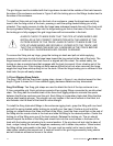
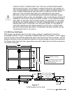
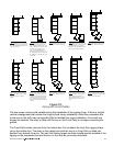
In this document and in the software modeling program, the front rigging fitting attachment
locations are denoted by the number of holes showing in the rigging track once a rigging strap is
installed. On each side of the enclosures at the front, there is a pin in the middle of the rigging
track that is used to secure the Front Dollies to the enclosures. When two enclosures are linked
together so that they are tight packed with the sides of the enclosures parallel, the rigging fittings
are installed near the middle of the rigging track in the last available rigging cutout next to the
dolly pins. In this case, there are no cutouts in the rigging track visible because the rigging fittings
and the chain cover up all of the track cutouts. Hence, this position is referred to a No Holes
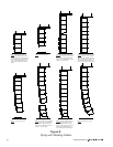
Showing. For example, when two rectangular Xvls enclosures are linked together using an Xvsl
linking strap, and a relative angle of 0° is required between the boxes (i.e., the boxes are tight
packed with both facing straight ahead), the rigging fittings of the Xvsl linking straps are installed
in the middle next to the dolly pins for No Holes Showing. If a relative angle of 2° is required
between the two Xvls boxes, then one of the rigging fittings must be moved one cutout in the
track, leaving One Hole Showing. If a relative angle of 4° is required, then one of the rigging
fittings must be moved two cutouts in the track, leaving Two Holes Showing.To get the correct
angle between two boxes, it does not matter on which box the holes are showing. It is even
possible to achieve the correct angle with holes showing on both boxes. However, there is an
advantage in always having the holes showing on the bottom box only. When standing on the
ground looking up at an array, the holes showing on the bottom box are always visible. If there are
holes open on the top box, they may not be visible from the ground, because the view of those
holes may be obstructed by the rigging fittings. Thus, it is always best to install the rigging fittings
on the top box in the rigging-track cutout next to the dolly pin with no holes showing on the top
box, then make all angle adjustments by changing the position of the rigging fitting in the track of
the bottom box.
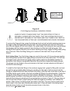
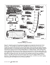
2.3 Deciding Whether to Use an Xvhg or Xvhl at the Grid
There are two pieces of rear rigging hardware and two pieces of front rigging hardware required
for this purpose. The front hardware consists of two Xvsg chain assemblies. There are two types
of rigging hardware, however, that may be used at the rear - either two Xvhg flexible-chain grid
hinges or two Xvhl solid-arm linking hinges. Xvhg chain grid hinges allow a flexible attachment to
the grid. This makes attachment to the grid faster; however, the grid will not be secure on top of
the loudspeakers during transportation. Xvhl solid-arm linking hinges allow a rigid attachment to
the grid. This makes attachment to the grid a bit slower; however, the height is less and the grid is
secured on top of the loudspeakers during transportation. The Xvhg offers a higher rigging
strength when the top box is angled down more than 20°, while the Xvhl offers greater rigging
strength when the top box is angled down less than 20°. (Note that the Xvhl linking hinge is the
same hardware used to link two enclosures together.) Either type of hardware will work for
attaching any of the loudspeaker systems to the grid.
The decision of whether to use the Xvhg or Xvhl for the rear rigging hardware is left to the user.
The Simplified Structural Ratings described in Section 3.3 always assumes the worst case (i.e.,
the lowest rating at any angle for either the Xvhg and Xvhl). This provides for quick evaluations
with the highest margin of safety, but does limit the amount of weight that can be suspended. If
the the Detailed Structural Ratings described in Section 3.4 are used, the user will find that a
greater amount of weight and greater angles are possible while maintaining a sufficient safety
factor. The X-Line modeling program will automatically calculate the structural capabilities using
the more detailed structural analysis based on which piece of hardware is selected for rear
attachment to the grid.
21