


ELECTRO-VOICE
®
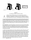
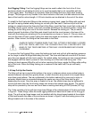
The rigging straps are shipped from the factory with chain connected in the A position on the
fittings on both ends. (This would be denoted as an A-A length.) When the chain is connected in
the B position on both fittings (known as the B-B length), the strap is 0.50 inches longer than
when connected in the A-A position. This 0.50-inch change in length results in a 1°-angle
adjustment. When the chain is connected in the A position on one fitting and the B position on
the other fitting (known as the A-B length), the strap is 0.25 inches longer than when connected
in the A-A position. This 0.25-inch change in length results in a 0.5°-angle adjustment. Thus, by
adjusting the length of the straps and selecting their attachment position on the enclosure front
track, the relative angles between boxes can be adjusted in 0.5° increments. When used with the
A-A length, even-numbered angles result (0°, 2°, 4°, 6°, etc.) when changing the attachment
position of the strap along the track, while odd-numbered angles result (1°, 3°, 5°, 7°, etc.) when
used with the B-B length. With A-B length, in between angles are achievable (0.5°, 2.5°, 4.5°,
etc.).
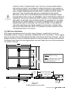
When planning angle adjustments between boxes, the shape of the enclosure must be taken into
account. Two rectangular enclosures (Xvls, Xsub,Xfil) can be pulled up tight with their sides
parallel, a 0° relative aiming angle exists between the enclosures (i.e., both are facing straight
ahead and the sound from both is aimed straight ahead). When two trapezoidal enclosures (Xvlt
only) are pulled up tight with their sides parallel, a 5° relative aiming angle exists between the
enclosures (because the enclosure shape is a 5° wedge, the sound from both is aimed 5° apart).
When a trapezoidal enclosure (Xvlt) and rectangular enclosure (Xvls, Xsub, Xfil1 or Xfil2) are
pulled up tight with their sides parallel, a 2.5° relative aiming angle exists between the enclosures.
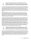
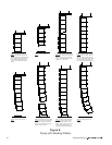
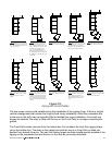
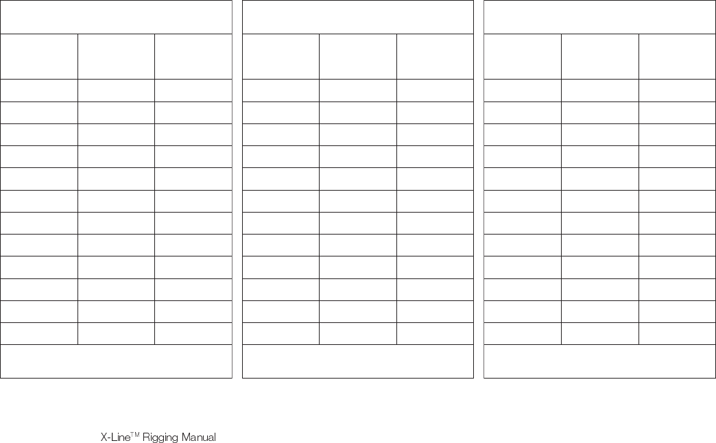
Figure 8 shows all of the possible combinations of rigging attachment locations and linking strap
lengths. When designing an array using the X-Line modeling software, the program will
automatically tell you what each front strap length is required (A-A, A-B or B-B) and at what
position on the rigging they should be attached for each enclosure.
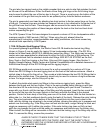
Figure 8:
Enclosure Vertical Angle Adjustments
ot)busXroslvX(xoBralugnatceR
)busXroslvX(xoBralugnatceR
elgnA
neewteB
sexoB
niahCtnorF
noitarugifnoC
gniwohSseloH
tnorFnI
gniggiR
°0.0A-A0
°5.0B-A0
°0.1B-B0
°0.2A-A1
°5.2B-A1
°0.3B-B1
°0.4A-A2
°5.4B-A2
°0.5B-B2
°0.6A-A3
°5.6B-A3
°0.7B-B3
:etoNselgnahtiwruccolliwspagcitsuoccA
.smetsysslvXneewteb°0.5nahtretaerg
ot)busXroslvX(xoBralugnatceR
)tlvX(xoBladiozeparT
elgnA
neewteB
sexoB
niahCtnorF
noitarugifnoC
gniwohSseloH
tnorFnI
gniggiR
°5.2B-A0
°0.3B-B0
°0.4A-A1
°5.4B-A1
°0.5B-B1
°0.6A-A2
°5.6B-A2
°0.7B-B2
°0.8A-A3
°5.8B-A3
:etoNselgnahtiwruccolliwspagcitsuoccA
.smetsystlvX&slvXneewteb°5.6nahtretaerg
ot)tlvX(xoBladiozeparT
)tlvX(xoBladiozeparT
elgnA
neewteB
sexoB
niahCtnorF
noitarugifnoC
gniwohSseloH
tnorFnI
gniggiR
°0.5B-B0
°0.6A-A0
°5.6B-A0
°0.7B-B1
°0.8A-A1
°5.8B-A1
°0.9B-B2
°0.01A-A2
°5.01B-A2
:etoNselgnahtiwruccolliwspagcitsuoccA
.smetsyStlvXneewteb°5.8nahtretaerg
20