


ELECTRO-VOICE
®
10
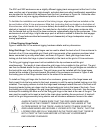
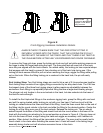
The Xfil1 and Xfil2 enclosures use a slightly different rigging track arrangement at the front. In this
case, another pair of proprietary high-strength, extruded aluminum-alloy track/bracket assemblies
are mounted on the sides of the enclosure near the front, as shown in Figure 3d. Unlike the other
models, there is only one rigging attachment position on these extrusions.
To facilitate the installation and removal of the linking hinges, alignment feet are installed on the
top and bottom of the X-Line enclosures. Male feet (protruding feet) are located on the bottom of
the enclosures, while female feet (concave dishes) are located on the top. When one enclosure is
stacked or lowered on top of another, the male feet on the bottom of the upper enclosure slide
into the female feet on the top of the lower enclosure, automatically aligning the enclosures. If the
enclosures do not self align, a light side-ways push is all that is needed to make the feet engage
and align. These features allow fast assembly and disassembly of large loudspeaker arrays in
touring applications.
1.3 Rear Rigging Hinge Details
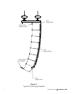
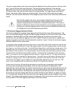
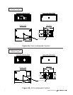
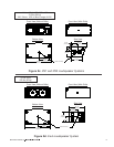
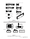
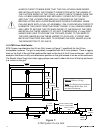
Figure 4 shows the X-Line external rigging hardware details and key dimensions.
Xvhg Grid Hinge: Two Xvhg grid hinges can be used to attach the back of an X-Line enclosure to
the back of an X-Line-compatible grid. Each grid hinge consists of two precision-machined steel
bases connected by an alloy-steel chain, as shown in Figure 4. Each grid-hinge base has a
locking pin that locks the hinge in place horizontally in the track on the grid or X-Line enclosure.
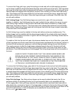
The Xvhg grid rigging hinges need not be installed in the top enclosure and the grid
simultaneously. The length of chain allows the grid hinges to be installed in the grid first. The grid
can then be floated above the top enclosure while the other ends of the grid hinges are installed in
the track at the rear of the enclosures. The grid hinges must be installed with the hinge bases
located at the outside of the track towards the sides of the enclosure as shown in Figure 5 with
the locking pins on the fittings located next to the sides of the enclosure.
To install an Xvhg grid hinge into the track of an enclosure, grasp one of the hinge bases and
firmly insert it into the long cutout in the track, pressing in until the spring-loaded locking pin is fully
retracted. Then apply pressure to slide the hinge base sideways towards the end of the track until
the spring-loaded locking pin drops into the hinge-locking-pin hole in the base of the track. Once
the locking pin is fully engaged, the grid hinge base will be immovable in the track. Use the same
technique for installing the other end of the Xvhg grid hinge in the track at the rear of the grid. The
user must be careful not to insert a twist in the chain when installing the second end. A twist will
result in the grid hinge assembly being shorter and will introduce excessive forces in the chain.
ALWAYS CHECK TO MAKE SURE THAT THE GRID HINGE BASES ARE
INSTALLED IN THE CORRECT ORIENTATION WITH THE HINGES AT THE
OUTSIDE EDGES OF THE TRACK. ALWAYS CHECK TO MAKE SURE THE
GRID-HINGE BASES ARE SECURELY LOCKED INTO THE TRACK, THAT THE
LOCKING PINS ARE FULLY ENGAGED IN THE TRACK AND THAT THERE IS
NOT A TWIST IN THE CHAIN BEFORE LIFTING ANY LOUDSPEAKER
ENCLOSURES OVERHEAD.