


ELECTRO-VOICE
®
14
ALWAYS CHECK TO MAKE SURE THAT THE GRID STRAP FITTING IS
SECURELY LOCKED INTO THE TRACK, THAT THE LOCKING PIN IS FULLY
SEATED INTO THE BASE OF THE TRACK AND THAT THERE IS NO TWIST IN
THE CHAIN BEFORE LIFTING ANY LOUDSPEAKER ENCLOSURE OVERHEAD.
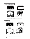
To remove the Xvsg grid strap, grasp the locking-pin knob and pull out while applying pressure on
the hinge to slide the hinge base along the track. The three stud feet will come out of the track
once they are aligned with the track cutouts. For added safety, the locking pin has a special shape
that engages with the track to prevent it from vibrating out of the track hole during use. If the
locking-pin knob seems difficult to pull out when removing the hinge, wiggle the fitting while pulling
out on the knob. When the fitting locking pin is centered in the track hole, the pin will easily
release.
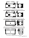
Xvsl Linking Strap: Two Xvsl linking straps are used to link a pair of X-Line enclosures together.
Each linking strap consists of two rigging fittings connected by an alloy-steel chain. The Xvsl has
the longest chain of the three front rigging straps to allow maximum adjustability between the
enclosures. Each fitting is a proprietary triple-stud fitting that has a large steel locating plunger.
The plunger not only locates in the round cutouts in the track, but also extends into the base of
the track for extra strength.
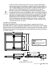
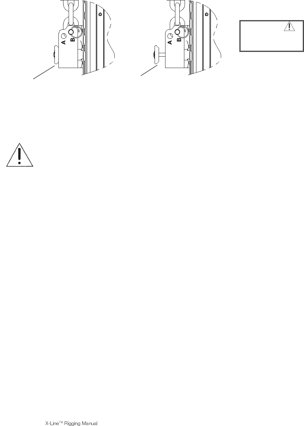
To install the Xvsl triple-stud fittings in the enclosure rigging track, grasp the fitting with one hand
and pull the spring-loaded safety locking pin out with your free hand. Continue to pull until the
locking pin retracts above the three stud feet of the fitting. Insert the three round feet on the end of
the fitting into the round cutouts in the track and slide the fitting to the desired position. Center the
locking pin of the fitting over one of the track cutouts. Release the locking pin. The pin should
extend beyond the bottom of the fitting and should lock into the round recess in the base of the
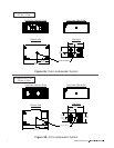
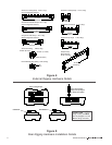
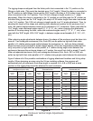
track with the locking pin retracting to its normal position as shown in Figure 6. If the pin does not
lock into the base of track, nudge it along the track and wiggle as necessary until it settles into
position. When locked, the fitting will be immovable in the track. The user must be careful not to
insert a twist in the chain when installing the second end. A twist will result in the linking hinge
assembly being shorter and will introduce excessive forces in the chain.
Figure 6:
Front Rigging Hardware Installation Details
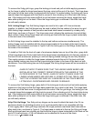
CAUTION
Locking Pins Must be Fully
Engaged In Track Before
Lifting Overhead
INCORRECT
CORRECT