


ELECTRO-VOICE
®
2. X-Line Rigging and Flying Techniques
2.1 Array Considerations
The X-Line loudspeaker systems have been specifically designed to construct acoustic line-
arrays. Line-array systems typically consist of independent columns of loudspeaker systems. The
most common implementation would be a stereo sound reinforcement system with two columns
(left and right). Additional columns of loudspeakers are sometimes added to cover different
seating sections of a venue seating areas that wrap around the side or back of a stage, for
example.
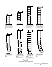
Vertical line arrays typically consist of several Xvls 90°H x 5°V systems at the top, followed by
several Xvlt 120°H x 8.5°V systems below. The exact number of Xvls and Xvlt loudspeaker
systems in a column will vary depending on the vertical acoustic coverage required for the specific
venue. Furthermore, the relative vertical angles between the boxes will also depend on the venue
acoustic coverage requirements. When acoustic coverage is required immediately below the
array, a single Xfil1 or Xfil2 downfill enclosure can be added at the very bottom of the array.
(Acoustic design techniques are outside the scope of this document and the reader is directed to
the X-Line modeling software available from the Electro-Voice website for acoustic design
assistance.) It is also possible to construct subwoofer line arrays using the Xsub systems.
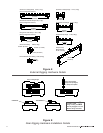
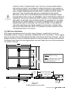
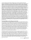
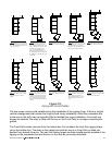
From Figure 2, the reader will note that X-Line full-range systems are not symmetrical left to right.
When constructing a line-array column, it is essential that all Xvls, Xvlt, Xfil1 and Xfil2 enclosures
are hung so that the high-frequency sections are all in a vertical straight line. In a stereo sound
reinforcement application, the best results are achieved when the boxes in the left and right arrays
are oriented so that the high-frequency sections are onstage (i.e., together towards the middle of
the venue), making the left and right arrays a perfect mirror image. This requires that the Xvls and
Xvlt loudspeaker systems on the house-right side be turned upside down. The grilles on the Xvls
and Xvlt boxes on the house-right side array should be rotated so a consistent appearance is
maintained between the left and right sides.
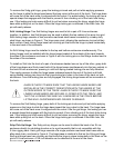
Because the downfill boxes cannot be turned upside down, the Xfil1 and Xfil2 loudspeaker
systems have been designed as a mirror image pair. Thus, in a stereo system, the Xfil1 would be
used at the bottom of the house-left side array, while the Xfil2 would be used on bottom of the
house-right side array.
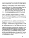
2.2 Adjusting the Vertical Angles of the Enclosures
The vertical angle of an enclosure may be adjusted relative to the enclosure immediately above
by choosing different attachment locations for the front linking straps in the enclosure track. The
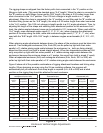
locating holes in the enclosure rigging track are spaced 1.00 inch (25.4 mm) apart. Moving the
attachment position one hole results in a 2° change in the enclosure vertical angle. However,
angle adjustments of 0.5° are possible.
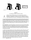
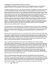
Each triple-stud fitting on the Xvsg, Xvsl and Xvsd front straps is attached to the chain with a pin
that passes through a hole on the fitting and through the last link on the end of the chain. Note
that there are two holes on each fitting that are labeled A and B. These two holes offer two
attachment points that change the length of the linking strap assembly.
19