


ELECTRO-VOICE
®
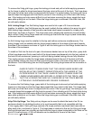
To remove the Xvhg grid hinge, grasp the locking-pin knob and pull out while applying pressure
on the hinge to slide the hinge base toward the long cutout at the end of the track. The hinge base
will come out of the track once it is aligned with the cutout. For added safety, the locking pin has a
special shape that engages with the track to prevent it from vibrating out of the track hole during
use. If the locking-pin knob seems difficult to pull out when removing the hinge, wiggle the hinge
base while pulling out on the knob. When the hinge locking pin is centered in the track hole, the
pin will easily release.
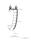
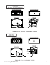
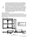
Xvhl Linking Hinge: Two Xvhl linking hinges are used to link a pair of X-Line enclosures
together. In addition, two Xvhl hinges may be used to attach the top cabinet of an array to a grid.
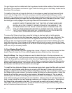
Each linking hinge consists of two precision-machined steel bases connected by a heavy-duty
steel hinge, as shown in Figure 4. The hinge arms pivot, allowing the enclosures to pivot at their
back corners. Each linking-hinge base has a locking pin that locks the hinge in place horizontally
in the rear track of the enclosure.
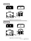
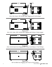
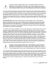
An Xvhl linking hinge must be installed in the top and bottom enclosures simultaneously. The
linking hinges must be installed with the hinge bases located at the outside of the track towards
the sides of the enclosure as shown in Figure 5 with the locking pins on the fittings located next to
the sides of the enclosure.
To install an Xvhl into the track of a pair of enclosures stacked one on top of the other, grasp both
of the hinge bases and firmly insert both of the hinge bases simultaneously into the long cutouts in
the track of both enclosures, pressing in until both spring-loaded locking pins are fully retracted.
Then apply pressure to slide the hinge bases sideways towards the end of the track until both
spring-loaded locking pins drop into the hinge-locking-pin holes in the base of the track on both
enclosures. Once the locking pins are fully engaged, the linking hinge bases will be immovable in
the track.
ALWAYS CHECK TO MAKE SURE THAT THE LINKING HINGE BASES ARE
INSTALLED IN THE CORRECT ORIENTATION WITH THE HINGES AT THE
OUTSIDE EDGES OF THE TRACK. ALWAYS CHECK TO MAKE SURE THE
LINKING HINGE BASES ARE SECURELY LOCKED INTO THE TRACK, AND
THAT THE LOCKING PINS ARE FULLY ENGAGED IN THE TRACK BEFORE
LIFTING ANY LOUDSPEAKER ENCLOSURES OVERHEAD.
To remove the Xvhl linking hinge, grasp both of the locking-pin knobs and pull out while applying
pressure on the hinge to slide the hinge base toward the long cutout in the track. The hinge base
will come out of the track once it is aligned with the cutout. Like the grid hinge, the locking pin has
a special shape that engages with the track to prevent it from vibrating out of the track hole during
use. If the locking-pin knob seems difficult to pull out when removing the hinge, wiggle the hinge
base while pulling out on the knob. When the hinge locking pin is centered in the track hole, the
pin will easily release.
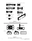
Xvhp Pick-Up Hinge: Two Xvhp pick-up hinges can be used to attach the back of an X-Line
enclosure directly to a building structure or to a grid assembly that is not compatible with the
X-Line rigging track. Each grid hinge consists of a single precision-machined steel base with an
alloy-steel chain, as shown in Figure 4. The hinge base is identical to that on the Xvhg grid hinge.
Each grid-hinge base has a locking pin that locks the hinge in place horizontally in the track on the
grid or X-Line enclosure. A 3/8-inch shackle can be attached to the end of the chain.
12