


ELECTRO-VOICE
®
4
1. X-Line Rigging System
1.1 Overview of the X-Line Flying System
The X-Line loudspeaker systems have been designed to construct acoustic line arrays. Acoustic
line arrays typically consist of independent columns of loudspeaker systems. Additional columns
are sometimes added to cover different seating sections of a venue. Unlike cluster systems, when
multiple line arrays are used, they are physically separated to minimize the acoustic overlap. This
simplifies the rigging system.
The X-Line loudspeaker enclosures utilize a hinged rigging system that makes constructing arrays
easy, predictable and repeatable. This rigging concept allows arrays to be constructed with
minimal spacing between enclosures. The enclosures are hinged at the back corners using
rigging hardware specially designed for the X-Line system. Adjustable rigging straps are installed
at the front of the enclosure allowing the space between the front corners to be adjusted; hence,
adjusting the relative angle between the enclosures.
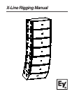
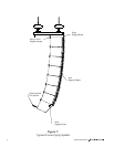
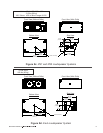
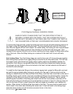
A basic array is shown in Figure 1 that illustrates the integral components that make up a typical
X-Line flying system. All of the flying X-Line loudspeaker systems utilize horizontal rigging-track
hardware on the back of the enclosure (at both the top and bottom) and vertical rigging-track
hardware on the front of the enclosures (at both the left and right sides).
Figure 1 illustrates an array column suspended with a grid. Like the loudspeaker systems, the grid
utilizes horizontal rigging-track hardware at the back and vertical rigging-track hardware at the
front like that on the enclosures. The top enclosure is secured to the grid with two quick-release
Xvhg grid hinges at the rear, and two quick-release Xvsg short chain rigging straps at the front.
The grid hinge has only one possible vertical attachment position on both the enclosure and the
grid. The front straps, however, have multiple vertical attachment positions to choose from on the
enclosure and one possible vertical attachment position on the grid. The grid hinges allow the
enclosure to pivot from its top back corner. The vertical angle of the top enclosure, relative to the
grid, is set by the linear position of the front rigging straps in the track on the front of the enclosure
and on the grid.
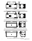
The second enclosure from the top, shown in Figure 1, is linked to the top enclosure with two
quick-release Xvhl linking hinges at the rear and two quick-release Xvsl long chain rigging straps
at the front. The linking hinges allow the lower enclosure to pivot from the back corner of the top
enclosure. The vertical angle of the bottom enclosure, relative to the top enclosure, is set by the
linear position of the front rigging straps in the track on the front of the top and bottom
enclosures. Additional enclosures may be linked together in the same fashion, as long as the
working-load limits for any of the enclosures, rigging hinges or straps are not exceeded. When
an Xfil1 or Xfil2 downfill is suspended from the bottom of the array, special-length Xvsd downfill
rigging straps are used at the front, while the standard Xvhl linking hinges are used at the rear.
An Xvbp pull-up bar may be attached to the rear rigging of the bottom box to adjust the vertical
tilt angle of the entire array.