


ELECTRO-VOICE
®
The array designer must be aware of the working-load limit ratings and the loads being applied to
the individual rigging points and the overall enclosure. An X-Line loudspeaker system is only as
strong as its weakest link. It is usually the case that one of the working-load limits will be
approached sooner than the other.
WHEN SUSPENDING ANY X-LINE LOUDSPEAKER SYSTEM OVERHEAD, THE
WORKING-LOAD LIMITS MUST NEVER BE EXCEEDED FOR EACH INDIVIDUAL
RIGGING POINT, OR THE OVERALL ENCLOSURE.
The forces acting on each individual rigging point and on the overall enclosures in an X-Line flying
system will vary with each array configuration. Determining the forces throughout an array
requires complex mathematical calculations. Electro-Voice engineers have, however, defined a
set of simplified structural-rating guidelines that eliminate the need for the complex calculations for
most array configurations. The interaction of the complex forces throughout arrays were analyzed
to develop this set of conservative guide-lines, presented below, to enable a rigger to immediately
determine on site whether or not an array is safe without having to make weight-distribution
calculations. The structural strength ratings of the individual rigging points and the overall X-Line
enclosures are also presented below so that a complex structural analysis can be made for any
array configuration. The reader should consult an experienced structural engineer to perform the
complex structural analysis.
The reader is directed to the References section of this manual for a list of rigging references (for
background in general rigging practice) and mechanical engineering references (for background in
structural engineering analysis).
3.3 Simplified Structural-Rating Guidelines
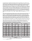
Electro-Voice engineers have defined a set of simplified structural-rating guide-lines that will
enable a rigger to immediately evaluate the safety of an X-Line system on site without having to
make complex force-distribution calculations. A combination of destructive testing and computer
modeling were used to analyze the complex forces throughout arrays. Conservative working-load
ratings were utilized to simplify the guidelines. Therefore, array configurations other than those
illustrated in these simplified guidelines may be permissible for those applications, consult section
3.4 Complex Structural-Rating Analysis for a detailed structural analysis.
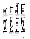
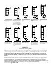
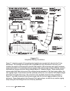
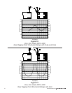
The simplified structural-rating guidelines are shown in Figure 11. (Note that there is a label on the
back of each flying X-Line loudspeaker enclosure that includes the graphics shown in Figure 11.)
These guidelines provide a simplified rating for typical arrays based on the:
1. Vertical tilt angle of each enclosure
2. Total weight of that enclosure plus all of the enclosures and rigging hung below it.
3. Side-to-Side Angles of the front Xvsg, Xvsl or Xvsf rigging straps
(or any custom front rigging straps) relative to the enclosures.
4. Side-to-Side Angles of the rear Xvhg grid hinges, Xvhl linking hinges or Xvhp pickup
hinges relative to the enclosures.
27