ELECTRO-VOICE
®
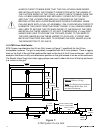
Once again, the array is lifted until the box on the Front Dolly is no longer contacting the ground
and the dolly is removed from the box. At this point, the next to last box is manually lifted and the
front Xvsl linking straps are attached between the box next to the bottom and the box above it.
This process is repeated as necessary to add more loudspeakers to the column. When the last
loudspeaker is in place at the bottom of the array, that box is manually lifted and the front Xvsl
linking straps are attached between it and the box above it.
2.5 Pull-Up Techniques
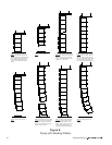
In cases where gravity does not allow the cabinets to be angled down as much as necessary to
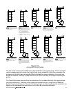
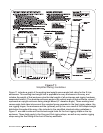
meet the acoustic coverage requirements, a pull-up assembly will be necessary. The Xvbp pull-up
bar (as described in Section 1.5) is recommended for this application. The Xvbp has two heavy-
duty fittings that can be attached to the bottom of the bottom cabinet. The user can then attach a
ratchet strap from the center eye ring on the Xvbp back up to the grid. The ratchet strap must only
be tightened until the slack in the front rigging chain hardware is eliminated and the chains are
taut. Attempting to tighten the pull-up assembly any tighter can introduce excessive forces in the
rigging hardware.
When larger downward angles are required for the top cabinets in the array, the pull-up assembly
will have to be attached behind the array (instead of the grid) to the building structure or a tower
structure. In this case, either a ratchet strap or another chain hoist may be used to pull back.
Again, the pull-up assembly must only be tightened until the slack is eliminated from the front
chains. If Xvhl solid-arm linking hinges are used to secure the top cabinet to the rear of the grid,
the user must never pull back so far that these hinges go into compression. If Xvhg chain hinges
are used to secure the top cabinet to the rear of the grid, the user must never pull back so far that
these hinge chains go slack. If front and back hoist motors are used to suspend the grid, the user
must never pull back so far that the rear hoist motor goes slack.
An Xvbp pull-up bar may be used for a column of up to 16 Xvls, Xvlt, Xsub, Xfil1 and/or Xfil2
cabinets. For a column of eight or less X-Line cabinets, two RS-1B fittings may be bridled together
(as described in Section 1.7) at the bottom of the bottom cabinet. A ratchet strap can then be
attached from the center of the bridle back up to the grid. The same techniques and cautions
described for the Xvbp above would apply to an RS-1B pull-up assembly.
The X-Line modeling program will tell the user when a pull-up assembly is required; however, the
program cannot tell the user when too much pull-up force has been applied. The user is
responsible for making sure an excessive pull-up force is not applied.
25


