


ELECTRO-VOICE
®
The grid also has rigging track on the middle crossbar that runs side to side that matches the track
on the rear of the enclosures. Either the Electro-Voice Xvhg grid hinge or the Xvhl linking hinge
may be used to attach the rear of the top box to the grid. There is a pad eye on the bottom of the
rear crossbar of the grid that may be used for an optional pull-up from the bottom enclosure.
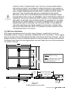
The grid is suspended over head by attaching two hoist motors to the two swivel rings on the top
of the grid. The swivel rings are mounted on hangers that are in turn attached to the center bar of
the grid that runs front to back. These hangers can be secured to the center bar at different
locations. Changing the position of these hangers adjusts the load on the front and back hoist
motors suspending the grid.
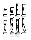
The ATM Flyware X-Line Grid was designed to suspend a column of X-Line loudspeakers with a
maximum weight of 3400 pounds (1542 kg). When using the grid, always follow the
manufacturers instruction, recommendations and safety precautions, and never exceed any
structural limits specified by ATM Flyware.
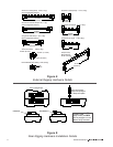
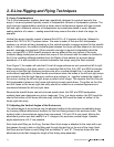
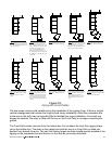
1.7 RS-1B Double-Stud Rigging Fitting
For special lightweight applications, the Electro-Voice RS-1B double-stud swivel-ring fitting
(shown in Figure 4) may be useful for rigging X-Line loudspeaker enclosures. (The RS-1B is
similar to the New Haven NH32102-2 double-stud swivel-ring fitting.) This fitting may be used on
custom wire-rope assemblies for attachment to either the front or the rear of the enclosure. The
reader is cautioned that the standard double-stud fittings ARE NOT AS STRONG as the Xvsl,
Xvsg, Xvsd or Xvsf front rigging or the Xvhp, Xvhg and Xvhl rigging hinges. (See Section 3.
Rigging Strength-Ratings, Safety Factors and Special Considerations for a detailed discussion of
the structural strength of the RS-1B fittings and the rigging hinges.)
RS-1B fittings would most commonly be used for a pull-up assembly for a column of X-Line.
Attach two RS-1B fittings to the rear rigging track on the back of the bottom enclosure. Attach a
ratchet strap to the grid for the pull up. Then create a bridle between the two RS-1B fittings that is
attached to the ratchet strap. This assembly should only be used for columns of eight enclosures
or less. For larger arrays, use the Xvbp pull-up bar.
To attach the double-stud swivel-ring fittings to the enclosure rigging track, grasp the fitting
between the thumb and first two fingers. Push in the spring-loaded safety locking pin with your
free hand and lift the outer locking ring over the pin by pressing with your thumb. Continue to
press with your thumb until the two legs of the fitting are fully exposed. Insert the two round feet
on the end of the legs into the round cutouts in the track and slide the fitting to the desired
position. Center the main body of the fitting over one of the track cutouts, with the feet located on
either side (i.e., the feet positioned directly under the teeth of the track). Release the outer locking
ring. The round protrusion on the bottom of the fitting should lock into the round cutout in the
track, with the locking ring retracting to its normal position, allowing the safety pin to reappear and
extend over the locking ring. If the fitting does not lock into the track, nudge it along the track and
wiggle as necessary until it settles into position. If the outer locking ring does not fully re-tract,
push the ring towards the track until the safety pin reappears and extends over the locking ring.
When locked, the fitting will be immovable in the track and the locking ring of the fitting may not be
lifted. To remove the fitting, reverse the procedure.
ALWAYS CHECK TO MAKE SURE THAT THE DOUBLE-STUD FITTING IS
SECURELY LOCKED INTO THE TRACK, AND THAT THE SAFETY PIN IS
EXTENDED OVER THE LOCKING RING BEFORE LIFTING ANY LOUDSPEAKER
ENCLOSURE OVERHEAD.
18