


ELECTRO-VOICE
®
ALWAYS CHECK TO MAKE SURE THAT THE PULL-UP-BAR HINGE BASES
ARE INSTALLED WITH THE CORRECT ORIENTATION WITH THE HINGES AT
THE OUTSIDE EDGES OF THE TRACK. ALWAYS CHECK TO MAKE SURE THE
PULL-UP-BAR HINGE BASES ARE SECURELY LOCKED INTO THE TRACK,
AND THAT THE LOCKING PINS ARE FULLY ENGAGED IN THE TRACK
BEFORE LIFTING ANY LOUDSPEAKER ENCLOSURES OVERHEAD. WHEN
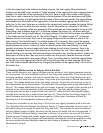
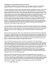
PULLING BACK WITH A PULL-UP ASSEMBLY, ONLY USE ENOUGH FORCE TO
ELIMINATE THE SLACK FROM THE FRONT CHAINS. IF Xvhl LINKING HINGES
ARE USED TO SECURE THE TOP ENCLOSURE TO THE REAR OF THE GRID,
NEVER ALLOW THESE HINGES TO GO INTO COMPRESSION. IF Xvhg GRID
HINGES ARE USED TO SECURE THE TOP ENCLOSURE TO THE REAR OF
THE GRID, NEVER ALLOW THESE HINGES TO GO SLACK. IF FRONT AND
BACK HOIST MOTORS ARE USED TO SUSPEND THE GRID, NEVER ALLOW
THE REAR MOTOR TO GO SLACK.
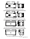
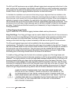
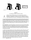
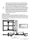
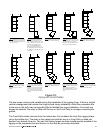
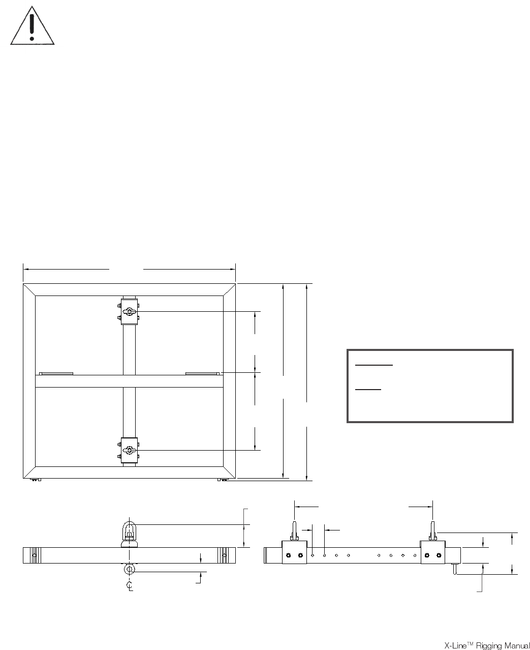
1.6 ATM X-Line Grid Details
ATM Flyware manufactures the X-Line Grid, shown in Figure 7, specifically for the X-Line
loudspeaker systems. The grid is completely compatible with the X-Line systems. There is rigging
track on the front of the grid that matches the track on the front of the X-Line enclosures - with the
exception that there is only one attachment position on the grid instead of six as on the enclosure.
The Electro-Voice Xvsg front chain rigging straps are used to attach the front of the top enclosure
in a column to the grid.
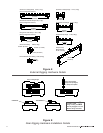
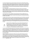
Figure 7:
ATM Flyware X-Line Grid
Weight: 260 lbs (118 kg)
Note: Grid Rigging track locations
are the same as the Xvls, Xvlt,
and Xsub Enclosures
17
53.000in
(1346mm)
15.182in
(386mm)
19.432in
(494mm)
48.614in
(1235mm)
49.239in
(1251mm)
2.062in
(52.4mm)
10.344in
(263mm)
5.719in
(145mm)
4.000in
(102mm)
3.000in (76.2mm)
TYP.
34.615in (879mm) MAX.
10.615in (270mm) MIN.