


31
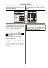
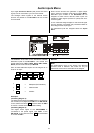
SURR (R) and
SURR (L)
Terminals for surround loudspeakers
1)
In a 5.1 system the right and left rear surround
loudspeakers are connected here; in a 7.1 system, the
side speakers.
/
Back
Rear loudspeaker terminals for 7.1 mode.
Note:
See
'
Wiring Diagrams 1
'
CENTER
Terminals for Centre loudspeaker
1)
The centre loudspeaker (if present) is connected to these
terminals. The speaker is located adjacent to the TV set
or screen.
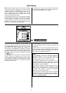
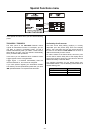
1)
Notes:
The impedance of the loudspeakers connected to the
surround receiver should not be less than 4 Ω (DIN
rating). The output stages are designed to cope with a
minimum load of 2 Ω, but if run for an extended period at
very high volume the high currents may cause the output
stages to overheat, which would cause the protective
circuit to switch them off automatically to prevent
damage.
It is important to ensure that the screw terminals are
firmly tightened, and that there are no stray strands of
wire which could cause short-circuits.
The accessory range includes a selection of high-
quality cables which are designed to match
equipment exactly.
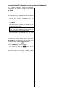
Note:
Only for countries where banana plugs are
approved for use as loudspeaker connections!
The red / black stoppers can be removed from the
loudspeaker terminals. The speakers can then be
connected using banana plugs.
The stoppers are simply a push-fit in the terminals, and
can be prised out from the rear using a suitable tool such
as a knife blade.
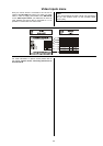
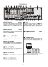
Mains input
The mains lead is connected to this socket. Be sure to
read the notes in the sections
'
Connecting the
equipment, using it for the first time
'
and
'
Safety
Notes
'
before you connect the equipment to the mains
supply.
R
LINK
Control outputs for connecting devices using the
R
LINK
control system. Both sockets are of equal status.
Digital OUTPUT
Digital audio signals are present at these sockets for
digital recorders or external processors.
Note:
Signals are only present here if a digital source device is
in use. The outputs are switched off when an analogue
source is in use.
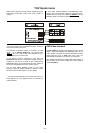
VCR 1
VCR 2
Socket area containing video recorder inputs and
outputs.
AUX AV 1
(STEREO CINCH and VIDEO)
AUX AV 2
(STEREO CINCH and VIDEO)
Inputs for connecting additional AV devices
(for YUV connections see
* Note
)
SET-TOP BOX
Sockets for a set-top box / sat. receiver
(see
'
Wiring Diagram 4
'
)
(for YUV connections see
* Note
)
DVD
Sockets for a DVD player
(see
'
Wiring Diagrams 2 and
3'
)
(for YUV connections see
* Note
)
* Note:
A YUV Component Video input can also be assigned to
any A/V source device (see section
'Configuration /
YUV inputs'
and
'Wiring Diagram 4').