


91
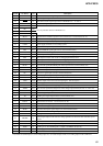
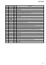
HCD-PX333
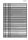
Pin No. Pin Name I/O Description
46 MD/CD POWER
O
Power down detection signal output to the MD mechanism controller (IC1001) and CD
mechanism controller (IC1101)
47 TR RELAY
O
Standby relay (RY991) control signal output (“L”: standby, “H” : power on)
PC LINK/KEY BOARD (CN104) ON/OFF control signal output (“H”: on, “L” : off)
48 RECMUTE
O Muting on/off control signal output of tape output signal “L”: muting on
49 DIMMER
O LCD back light on/off control signal output “H”: LED on
50 GC POWER
O Not used (open)
51 KBD CHK
I Key board check signal input terminal
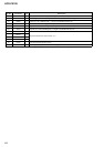
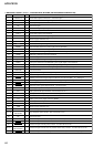
52
LED MD-PAUSE
O LED drive signal output of the X (MD) indicator (D605) “H”: LED on
53 LED MD-PLAY
O LED drive signal output of the N (MD) indicator (D604) “H”: LED on
54
LED CD-PAUSE
O LED drive signal output of the X (CD) indicator (D603) “H”: LED on
55 LED CD-PLAY
O LED drive signal output of the N (CD) indicator (D602) “H”: LED on
56 LED MD-REC
O LED drive signal output of the REC indicator (D606) “H”: LED on
57 LED STANDBY
O LED drive signal output of the I/1 indicator (D601) “H”: LED on
58 BVDD
— Power supply terminal (+5V)
59 BVSS
— Ground terminal
60 LED DATA
O Serial data output terminal for LED driver Not used (open)
61 LED CLK
O Serial data transfer clock signal output terminal for LED driver Not used (open)
62 LED CE1
O Chip select signal output terminal for LED driver Not used (open)
63 LED CE2
O Fan motor (M901) drive signal output “H”: fan motor on
64 LED CLEAR O
Reset signal output terminal for LED driver Not used (open)
65, 66 FUNC1, FUNC2 O
Function selection signal output terminal Not used (open)
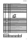
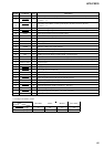
67
HEADPHONE IN
I
Headphone in detection signal input “H”: headphone in
68 ENC VOL A I
Jog dial pulse input from the rotary encoder A phase input Not used (fixed at “L”)
69 ENC VOL B I
Jog dial pulse input from the rotary encoder B phase input Not used (fixed at “L”)
70 ENC JOG 1A I
Jog dial pulse input from the rotary encoder A phase input Not used (fixed at “L”)
71 ENC JOG 1B I
Jog dial pulse input from the rotary encoder B phase input Not used (fixed at “L”)
72, 73
DEVICE3,
DEVICE2
— Not used (fixed at “L”)
74 AVDD
— Power supply terminal (+5V)
75 AVSS
— Ground terminal
76 AVREF
I Reference voltage (+5V) input terminal
77, 78
LID SW1,
LID SW2
I Switch input terminal Not used (fixed at “L”)
79 to 82
DIST 1 to DIST 4
I Model destination setting terminal
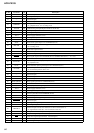
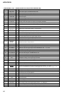
83 LEVEL-L
I L-ch level input terminal Not used (fixed at “L”)
84 LEVEL-R
I L-ch level input terminal Not used (fixed at “L”)
85 KEY1
I
Key input terminal (A/D input) S601 to S606 (I/1, x (CD), N X CD, M >,
TUNING +, VOLUME –, VOLUME + keys input)
86 KEY2
I
Key input terminal (A/D input) S621 to S628 (. m TUNING –, FUNCTION,
PLAY MODE TUNING MODE, REPEAT STEREO/MONO, REC MODE, REC/REC IT,
CD SYNC NORMAL, CD SYNC HIGH keys input)
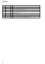
87 KEY3
I
Key input terminal (A/D input) S631 to S637 (Z MD, x (MD), . m, N X MD,
M >, Z CD, TUNER/BAND keys input)
88 KEY4
I Key input terminal (A/D input) Not used (fixed at “H”)
89
NMI I Non-maskable interrupt input terminal Fixed at “L” in this set
90 KBD CLK
I Key board data reading clock signal input terminal
91 KEY RM INT
I Interrupt signal input from function keys or remote control receiver