


88
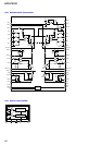
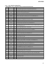
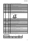
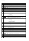
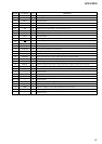
HCD-PX333
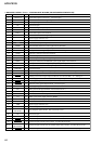
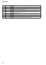
• MD DIGITAL BOARD IC1101 µPDSS3033AYGF-M10-3BA (CD MECHANISM CONTROLLER)
Pin No. Pin Name I/O Description
1
DRVDAT O Serial data output to a FL driver Not used (open)
2
DRVCLK O Serial data transfer clock signal output to a FL driver Not used
3
I2CDAT I Data input/output terminal for the IIC bus
4
NC O Not used (open)
5
I2CCLK I Shift clock signal input/output terminal for the IIC bus
6
GND — Ground terminal
7
DATA O Serial data output to the CD block
8
CLK O Serial data transfer clock signal output to the CD block
9 EVDD
— Power supply terminal (+5V)
10
EVSS — Ground terminal
11
XLT O Serial data latch pulse output to the CD block
12
SENSE I Internal status detection monitor input from the CD block
13
LDON O Laser diode on/off control signal output to the CD block
14
LPH O Laser power control signal output terminal Not used (open)
15
SUBQ I Subcode Q data input from the CD block
16
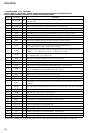
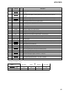
NC
O
Not used (open)
17
SQCLK
O
Subcode Q data reading clock signal output to the CD block
18 CTRL1
O Disc speed selection (normal/double speed) signal output to the CD block
19 X4
O Disc speed selection (normal/quadruple speed) signal output to the CD block
20
8CM O CD disc size select (8cm/12cm) signal output terminal Not used (open)
21
GND/VPP — Ground terminal
22 SPINDLEMUTE
O Spindle motor muting control signal output to the CD block “H”: muting on
23 to 29
NC O Not used (open)
AMUTE
30 O
Muting on/off control signal output to the D/A converter (IC1006) “L”: muting on
31 BDPWR O
Power supply for the CD block on/off control signal output “H”: power on
32 BDRST
O Reset signal output to the CD block
33 FUNC ST
O Function select signal output terminal Not used (open)
34 RESET
I Reset signal input from the system controller (IC501)
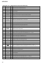
35
XT1 I Sub system clock input terminal Not used (fixed at “L”)
36
XT2 O Sub system clock output terminal Not used (open)
37
CHEMICON I Connected to the external capacitor
38
X2 O Main system clock output terminal (16MHz)
39
X1 I Main system clock input terminal (16MHz)
40
VSS — Ground terminal
41 VDD
— Power supply terminal (+5V)
42
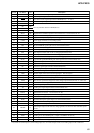
NC — Not used (open)
43 to 45
ENCODE0 to
ENCODE2
I Jog dial pulse input terminal Not used (fixed at “H”)
46
NC O Not used (open)
47
TRAYSENCE3 I Detection input from the disc tray address detect rotary encoder Not used (fixed at “H”)
48 CNT-SW
I Detection input from the count detect switch Not used (fixed at “H”)
49 PRTC-SW
I Detection input from the protect switch Not used (fixed at “H”)
50, 51
TRAYSENS1,
TRAYSENS2
I Detection input from the disc tray address detect rotary encoder Not used (fixed at “H”)
52 OUT-SW I
Detection input from the tray open/close detect switch (S1) “L”: when tray is open