


43
HCD-PX333
7. INITIAL SETTING OF ADJUSTMENT VALUE
Note:
Mode which sets the adjustment results recorded in the non-volatile
memory to the initial setting value. However the results of the tempera-
ture compensation offset adjustment will not change to the initial setting
value.
If initial setting is performed, perform all adjustments again excluding the
temperature compensation offset adjustment.
For details of the initial setting, refer to “4. Precautions for Adjustments”
(See page 39) and execute the initial setting before the adjustment as re-
quired.
Procedure:
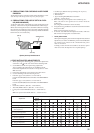
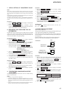
1. Press the . “R” or > “R” button to display “ADJ CLEAR”
(C28).
2. Press the ENTER/YES “R” button. “Complete!” will be
displayed momentarily and initial setting will be executed, after
which “ADJ CLEAR” (C28) will be displayed.
8. RECORDING AND DISPLAYING THE IOP
INFORMATION
The IOP data can be recorded in the non-volatile memory. The IOP
value on the optical pick-up label and the IOP value after the
adjustment will be recorded. Recording these data eliminates the
need to read the label on the optical pick-up.
Recording Procedure:
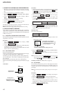
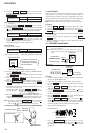
1. Press the . “R” or > “R” button to display “Iop Write”
(C05), and press the ENTER/YES “R” button.
2. The display becomes “Ref=@@@.@” (@ is an arbitrary
number) and the numbers which can be changed will blink.
3. Input the IOP value on the optical pick-up label.
To select the number: Press the
. “R” or > “R” button.
To select the digit :Press the
[CD SYNC NORMAL] button
so that "IT" is displayed. Then press the
[REC MODE] button.
Press the [REC MODE] button.
4. When the ENTER/YES “R” button is pressed, the display
becomes “Measu=@@@.@” (@ is an arbitrary number).
5. As the adjustment results are recorded for the step 4 value. Leave
it as it is and press the ENTER/YES “R” button.
6. “Complete!” will be displayed momentarily. The value will be
recorded in the non-volatile memory and the display will become
“Iop Write” (C05).
Display Procedure:
1. Press the . “R” or > “R” button to display “IopRead”(C26).
2. “@@.@/##.#” is displayed and the recorded contents are
displayed.
@@.@ indicates the IOP value on the optical pick-up label.
##.# indicates the IOP value after adjustment
3. To end, press the MENU/NO “R” button to display “Iop Read”
(C26).
9. TEMPERATURE COMPENSATION OFFSET
ADJUSTMENT
Save the temperature data at that time in the non-volatile memory
as 25 ˚C reference data.
Note:
1. Usually, do not perform this adjustment.
2. Perform this adjustment in an ambient temperature of 22 ˚C to 28 ˚C.
Perform it immediately after the power is turned on when the internal
temperature of the unit is the same as the ambient temperature of 22 ˚C
to 28 ˚C.
3. When D101 has been replaced, perform this adjustment after the tem-
perature of this part has become the ambient temperature.
Procedure:
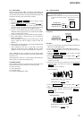
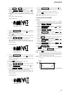
1. Press the . “R” or > “R” button to display “TEMP
ADJUST” (C03).
2. Press the
ENTER/YES “R” button to select the “TEMP
ADJUST” mode.
3. “TEMP =
[OK]” and the current temperature data will be
displayed.
4. To save the data, press the ENTER/YES “R” button.
When not saving the data, press the MENU/NO “R” button.
5. When the ENTER/YES “R” button is pressed, “TEMP =
SAVE” will be displayed and turned back to “TEMP ADJUST”
(C03) display then. When the MENU/NO “R” button is pressed,
“TEMP ADJUST” (C03) will be displayed immediately.
Specified Value:
The “TEMP = ” should be within “E0 - EF”, “F0 - FF”, “00 -
0F”, “10 - 1F” and “20 - 2F”.
10.LASER POWER ADJUSTMENT
Before starting adjustment;
The laser power adjustment value changes depending upon the types
of the optical pick-up (KMS-262A or KMS-262E).
Check the type of the optical pick-up before starting adjustment.
(See the illustrations “The method of identifying the optical pick-
up on page 44.)
Check the IOP value of the optical pick-up before adjustments.
(Refer to 8. Recording and Displaying the Iop Information)
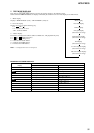
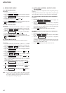
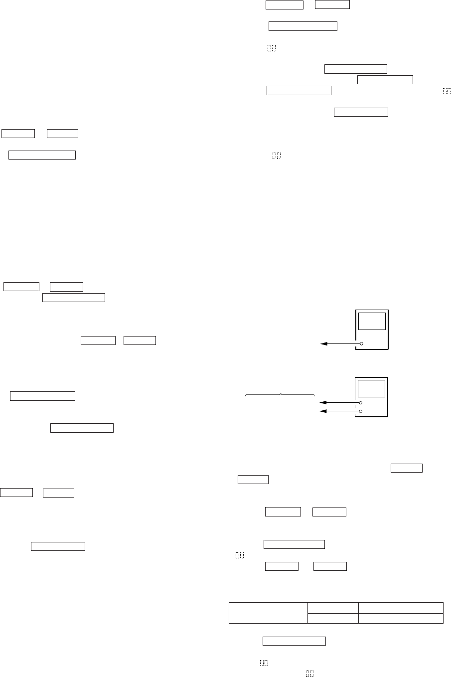
Connection:
Procedure:
1. Insert the laser power meter probe into the disk insertion slot
and set it on top of the objective lens of the optical pick-up.
(When it cannot be set properly, press the
m “R” button
or M “R” button to move the optical pick-up)
Connect the digital voltmeter to CN105 pin 1 (I+3V) and
CN105pin 2 (IOP) on the BD (MD) board.
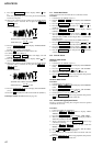
2. Press the . “R” or > “R” button to display “LDPWR
ADJUST” (C04).
(Laser power : For adjustment)
3. Press the ENTER/YES “R” button once to display “LD 0.9 mW
$ ”.
4. Press the . “R” or > “R” button until the laser power
meter reading matches with the specified value as described in
the following table.
Press the ENTER/YES “R” button after setting the range knob
of the laser power meter, and save the adjustment results. (“LD
SAVE $ ” will be displayed for a moment)
5. Then “LD 8.4 mW $ ” will be displayed.
Optical pick-up
objective lens
laser
power meter
+
–
BD (MD) board
digital voltmeter
CN105 pin
1
(I+3V)
CN105 pin
2
(IOP)
SPECIFIED VALUE
KMS-262A
KMS-262B
0.85 to 0.91 mW
0.90 to 0.95 mW