


Page 24 of 78
i n t e l l i g e n t w i r e l e s s p l a t f o r m
airClient™ Nexus PRO TOTAL User Guide
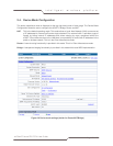
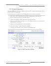
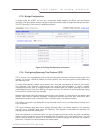
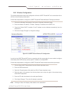
2.7.3. Bridge Configuration
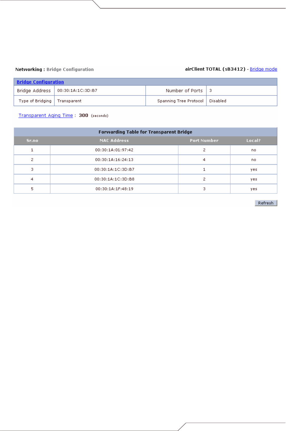
In Bridge mode the aCNPT unit acts as a transparent bridge between the Radio and the Ethernet
interfaces. The figure below shows the bridge configuration and the table of bridge forwarding information.
The STP (Spanning Tree Protocol) is disabled by default.
Figure 2-13 Bridge Configuration Information
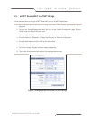
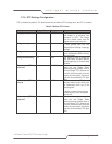
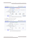
2.7.4. Configuring Spanning Tree Protocol (STP)
STP is a Layer 2 link management protocol that provides path redundancy while preventing loops in the
network. For a Layer 2 Ethernet network to function properly, only one active path can exist between any
two redundant links.
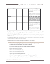
To create a fault-tolerant network, there needs to be a loop-free path between all nodes in the network.
The Spanning Tree Algorithm calculates the best loop-free path throughout a Layer 2 network.
Infrastructure devices such as wireless bridges and switches send and receive spanning tree frames,
called Bridge Protocol Data Units (BPDUs), at regular intervals. The devices do not forward these frames
but use them to construct the loop-free path.
Multiple active paths among end stations cause loops in the network. If a loop exists in the network, end
stations might receive duplicate messages. Infrastructure devices might also learn end-station MAC
addresses on multiple Layer 2 interfaces. Such conditions result in an unstable network.
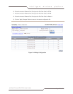
STP defines a tree with a root bridge and a loop-free path from the root to all infrastructure devices in the
Layer 2 network.
STP forces redundant data paths into a standby (blocked) state. If a network segment in the spanning
tree fails and a redundant path exists, the Spanning Tree Algorithm recalculates the spanning tree
topology and activates the standby path.
When two interfaces on a device are part of a loop, the spanning tree port priority and path cost settings
determine which interface is put in the forwarding state and which is put in the blocking state. The port
priority value represents the location of an interface in the network topology and how well it is located to
pass traffic. The path cost value represents the media speed.