


31
Connecting
—Continued
Notes:
• Before making any connections, turn off the
DV-SP1000/DV-SP1000E and your TV and discon-
nect their power cords from the wall outlets.
• Also refer to the hookup pages in your TV’s manual.
• Connect the DV-SP1000/DV-SP1000E’s video out-
puts directly to your TV. Don’t connect a VCR or other
video equipment in between. Doing so may result in
picture distortion, because of the copy protection sys-
tem used on DVD-Video discs.
• See the tables on page 27 for details on how the
DV-SP1000/DV-SP1000E outputs video and audio
from each output.
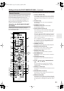
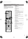
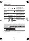
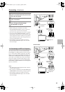
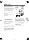
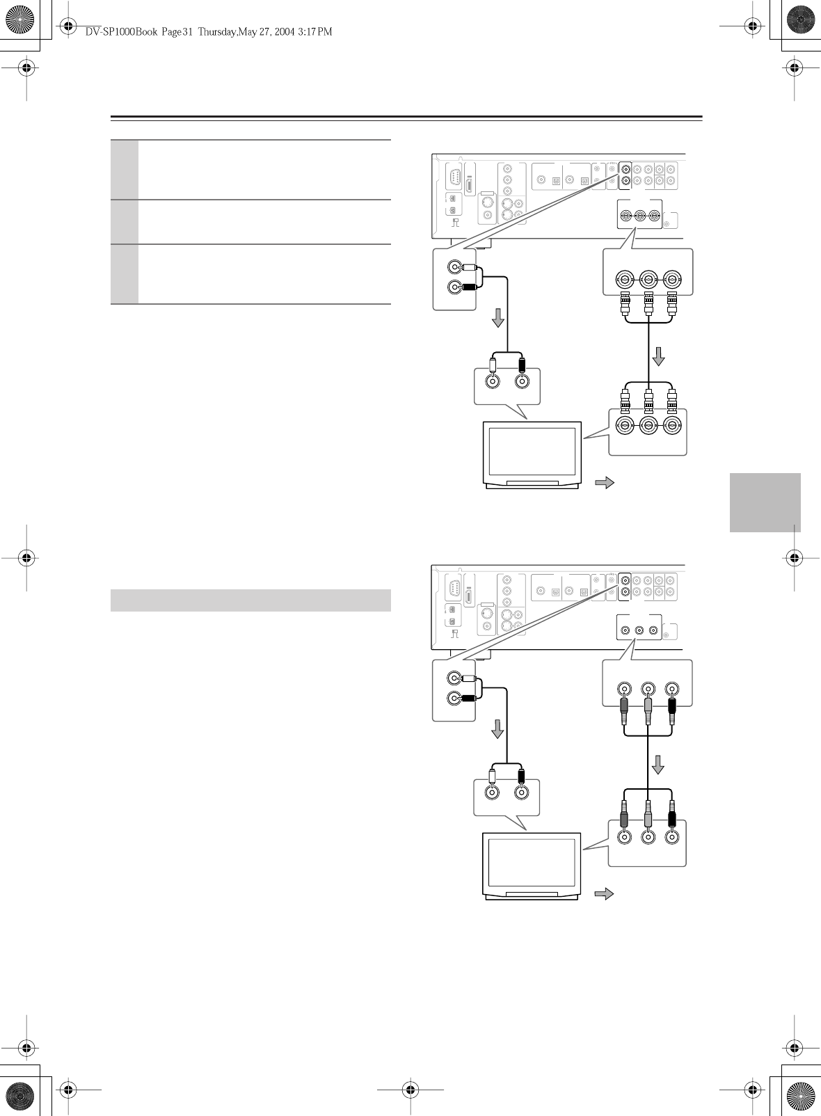
This section shows how to connect the DV-SP1000/
DV-SP1000E to an HDTV (plasma, LCD) or projector.
Use a commercially available component video cable
(BNC) to connect the DV-SP1000/DV-SP1000E’s HD
VIDEO OUT COMPONENT socket to a component
video input on your HDTV. (If you have the Canadian
model, use an RCA component video cable.) Use the
supplied AV cable (RCA) to connect the DV-SP1000/
DV-SP1000E’s D.MIX AUDIO OUT to an analog audio
input on your HDTV.
Notes:
• The yellow plugs on the supplied AV RCA cable are
not used in this example.
• Don’t connect a standard TV to the HD VIDEO OUT
COMPONENT socket, because you’ll get no picture.
• See the tables on page 27 for details on how the
DV-SP1000/DV-SP1000E outputs video and audio
from each output.
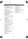
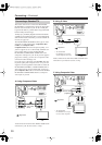
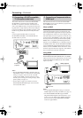
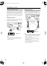
Canadian Model
1
Turn off the DV-SP1000/DV-SP1000E and
your TV, and disconnect their power cords
from the wall outlets.
2
Connect the DV-SP1000/DV-SP1000E to
your TV as shown.
3
When you’ve completed all connections,
see “Turning On the DV-SP1000/
DV-SP1000E” on page 42.
D. Connecting an HDTV or Projector
OUT
D. MIX FRONT SURR
1
CENTER SURR
2
L
R
L
R
SUB
WOOFER
IN
REMOTE
CONTROL
VIDEO
OUT
COMPONENT
S
VIDEO VIDEO
Y
P
B
PR
1
+
21
RS
232
IR
SURR
MODE
(
AUDIO OUT
)
IN
12
V
TRIGGER
YPB PR
COAXIAL OPTICAL OPTICALCOAXIAL
DIGITAL
1
DIGITAL
2
VIDEO
S
VIDEO
HDMI
VIDEO
IN
AUDIO
OUT
HD VIDEO
OUT
COMPONENT
AUDIO
OUT
S400
(
AUDIO
)
OUT
YPB PR
YPB PR
COMPONENT
COMPONENT IN
D. MIX
L
R
AUDIO
OUT
LR
ANALOG INPUT
HDTV, projector
Component
video cable
(BNC)
(white)
(red)
Signal flow
(white)
(red)
AV RCA cable
(supplied)
OUT
D. MIX FRONT SURR
1
CENTER SURR
2
L
R
L
R
SUB
WOOFER
IN
REMOTE
CONTROL
VIDEO
OUT
COMPONENT
S
VIDEO VIDEO
Y
P
B
PR
1
+
21
RS
232
IR
SURR
MODE
(
AUDIO OUT
)
IN
12
V
TRIGGER
COAXIAL OPTICAL OPTICALCOAXIAL
DIGITAL
1
DIGITAL
2
VIDEO
S
VIDEO
HDMI
VIDEO
IN
AUDIO
OUT
AUDIO
OUT
S400
(
AUDIO
)
OUT
YPB PR
HD VIDEO
OUT
COMPONENT
YPB PR
YPB PR
COMPONENT
COMPONENT IN
D. MIX
L
R
AUDIO
OUT
LR
ANALOG INPUT
HDTV, projector
Component
video cable
(RCA)
(white)
(red)
Signal flow
(white)
(red)
AV RCA cable
(supplied)