


21
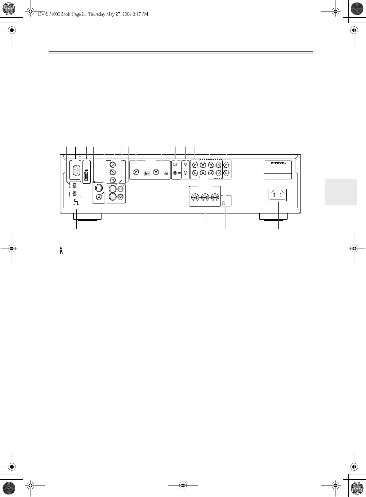
Getting to Know the DV-SP1000/DV-SP1000E
—Continued
M
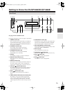
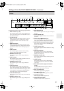
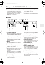
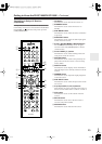
SURR MODE (AUDIO OUT) switch (37)
This switch is used to set the surround output mode
of the analog multichannel audio outputs. If you
connect the SURR 2 outputs to a 7.1-channel AV
receiver or amp, set this switch to 1+2. This reduces
the output level by 3 dB. If you’re not using the
SURR 2 outputs, set this switch to 1.
N
HD VIDEO OUT COMPONENT (31)
These RCA sockets output HD component video
and can be connected to the HD component video
input on an HDTV or projector.
O
AC INLET (41)
The supplied power cord should be connected here.
■
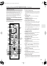
Other Models
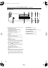
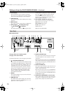
A
i.LINK S400 (AUDIO) (35)
These sockets can output up to
six channels and up
to 192 kHz/24-bit digital audio in
i.LINK format
and can be connected to the i.LINK
sockets
on a
compatible AV receiver or other component. The
actual output signal depends on the disc currently
playing. Since
i.LINK is a bidirectional connec-
tion, connected components can talk to each
other for optimal setup and perfectly synchro-
nized audio transmission.
B
RS 232
This bidirectional RS-232 port can be connected to
an external controller.
C
HDMI OUT (32)
This HDMI socket outputs digital video and audio
and can be connected to an HDMI input on a com-
patible TV or other component.
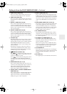
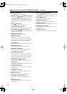
D
VIDEO IN S VIDEO (39)
This input accepts S-Video and can be connected to
an S-Video output on a TV, camcorder, or other
component.
When the video input source is set to EXTERNAL,
video signals received here are upconverted to pro-
gressive video and output by the HD VIDEO OUT
COMPONENT output.
E
VIDEO IN VIDEO (39)
This input accepts composite video and can be con-
nected to a composite video output on a TV, cam-
corder, or other component.
When the video input source is set to EXTERNAL,
video signals received here are upconverted to pro-
gressive video and output by the HD VIDEO OUT
COMPONENT output.
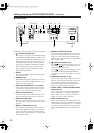
F
VIDEO OUT COMPONENT (Y, P
R
, P
B
) (30)
These sockets output component video and can be
connected to a component video input on a TV or
projector. They output only interlaced video.
G
VIDEO OUT S VIDEO (30)
These two sockets output S-Video and can be con-
nected to an S-Video input on a TV or projector.
H
VIDEO OUT VIDEO (30)
These two sockets output composite video and can
be connected to a composite video input on a TV or
projector.
I
DIGITAL 1 AUDIO OUT (36, 38)
These sockets output digital audio and can be con-
nected to the digital audio input on a hi-fi amp, AV
receiver, surround sound decoder (Dolby Digital,
DTS), or other component. There’s a coaxial output
and an optical output.
J
DIGITAL 2 AUDIO OUT (36, 38)
These sockets output digital audio and can be con-
nected to the digital audio inputs on a hi-fi amp, AV
receiver, surround sound decoder (Dolby Digital,
DTS), or other component. There’s a coaxial output
and an optical output.
OUT
AC INLET
D. MIX FRONT SURR
1
CENTER SURR
2
L
R
L
R
SUB
WOOFER
OUT
IN
REMOTE
CONTROL
VIDEO
OUT
COMPONENT
S
VIDEO VIDEO
Y
P
B
PR
1
+
21
RS
232
IR
S400
(
AUDIO
)
SURR
MODE
(
AUDIO OUT
)
IN
12
V
TRIGGER
SUPER AUDIO CD & DVD AUDIO/
VIDEO PLAYER
MODEL NO. DV
-
SP
1000
YPB PR
COAXIAL OPTICAL OPTICALCOAXIAL
DIGITAL
1
DIGITAL
2
VIDEO
S
VIDEO
HDMI
VIDEO
IN
AUDIO
OUT
HD VIDEO
OUT
COMPONENT
AUDIO
OUT
N
5
9K
RQ
S
O
M
L
67
8
1B 34 J
P