


22
Getting to Know the DV-SP1000/DV-SP1000E
—Continued
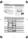
K
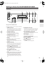
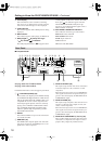
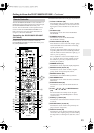
IR IN/OUT (40)
The IR IN socket can be used to connect a commer-
cially available IR receiver, which can be used to
pickup signals from the remote controller when the
DV-SP1000/DV-SP1000E is located in another
room, installed in a rack, or is out of range of the
remote controller
The IR OUT connector can be used to connect a
commercially available IR emitter, which can be
used to pass remote controller signals received by
the IR IN along to other components.
L
REMOTE CONTROL (40)
These (Remote Interactive) sockets can be con-
nected to the sockets on other Onkyo AV com-
ponents for interactive control.
To use you must make an analog audio connec-
tion between the DV-SP1000/DV-SP1000E and
your Onkyo AV receiver, even if they are connected
digitally.
M
D.MIX AUDIO OUT (30, 31, 38)
These sockets output analog audio and can be con-
nected to a stereo analog audio input on a TV, hi-fi
amp, or other component. If the source audio is
multichannel (Dolby Digital, DTS, DVD-Audio,
SACD), they output a 2-channel downmix.
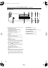
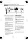
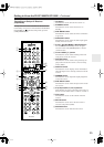
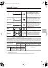
N
FRONT, SURR 1, CENTER & SUBWOOFER
AUDIO OUT (37)
These sockets output 5.1-channel analog audio and
can be connected to a 5.1-channel analog audio
input on an AV receiver, surround sound decoder
(Dolby Pro Logic), or other component.
O
SURR 2 AUDIO OUT (37)
These sockets output the same analog audio as the
SURR1 outputs and can be connected to the analog
surround back left and right inputs on a 7.1-channel
AV receiver or other component. When using these
sockets, the SURR MODE switch should be set to
1+2.
P
SURR MODE (AUDIO OUT) switch (37)
This switch is used to set the surround output mode
of the analog multichannel audio outputs. If you
connect the SURR 2 outputs to a 7.1-channel AV
receiver or amp, set this switch to 1+2. This reduces
the output level by 3 dB. If you’re not using the
SURR 2 outputs, set this switch to 1.
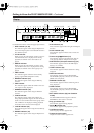
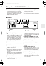
Q
HD VIDEO OUT COMPONENT (31)
These BNC sockets output HD component video
and can be connected to the HD component video
input on an HDTV or projector.
When a video signal is fed to a VIDEO IN socket
(S-Video or composite), and the video input source
is set to EXTERNAL, that video signal is upcon-
verted to progressive and output here.
R
12V TRIGGER IN
This socket can be connected to the 12-volt trigger
output on an AV receiver or other component so that
the DV-SP1000/DV-SP1000E can be turned on
remotely.
S
AC INLET (41)
The supplied power cord should be connected here.