6.1 GOT Main Unit
6.1.3 Wiring method
6 - 7
1
OVERVIEW
2
SYSTEM
CONFIGURATION
3
PERFORMANCE
4
NAMES OF
THE PARTS AND
THEIR SETTINGS
5
ROUGH
PRE-OPERATION
PROCEDURE
6
HANDLING
7
MAINTENANCE AND
INSPECTION
8
EMC DIRECTIVE
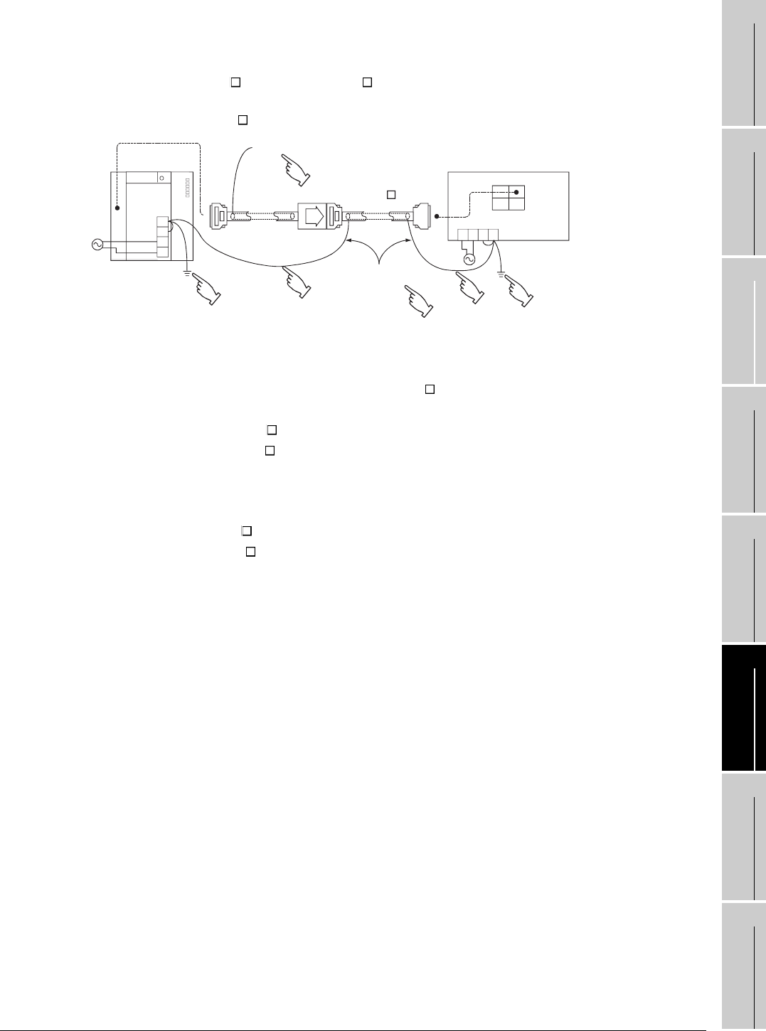
2) Connection Cable Wiring
• Do not bind connection cables with the main circuit (high voltage, heavy current) or I/O signal
cables, or lay them close to each other.
• When using A8GT-C EXSS-1 or A8GT-C BS, ground wires as below.
(1) When using A8GT-C EXSS-1 cable
1) Connect the LG and FG terminals of GOT unit power to the ground through the terminal
block with one wire.
2) Use FG wires of 28 cm or less for the A8GT-C BS cable.
3) Do not connect the FG grounding wire of A8GT-EXCNB cable.
4) Connect the A8GT-C BS cable's FG wire to FG of the GOT unit power terminal block.
5) Connect the A8GT-C BS cable's FG wire on the PLC side to FG of the PLC power supply
module.
6) Connect the LG and FG terminals of the terminal block on the PLC to ground with one wire.
(2) When using A8GT-C BS cable
Connect the A8GT-C BS cable's FG wires on the both sides to the FG terminals on the power
terminal block of the both side GOTs.
FG
LG
N
L
PLC
Disconnected
(A8GT-EXCNB)
GOT
OUT IN
FGLG
NL
2SQ wire FG terminal,
28 cm or less
(A8GT-C BS)
6)
5)
2)
4)
1)
3)


