


2 - 12
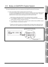
2.6 Notes on Q4ARCPU Duplex System
(2) Notes on 5V DC supply for the additional base (A68RB) for duplex system at the final stage:
220mA of current to be consumed will be supplied from the additional base for duplex system at the
final stage to the GOT bus interface, if the GOT power supply is off and the power supply for the
power supply module mounted on the additional base for duplex system at the final stage is on.
Therefore, please make sure that the 5V DC consumption (8A) of the power supply module will not
be exceeded by the sum of the value of the current consumption of the input/output module and
special function module that are mounted on the additional base for duplex system at the final
stage and the value of the current consumption (220mA) of the GOT bus interface.
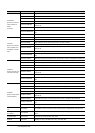
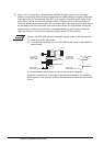
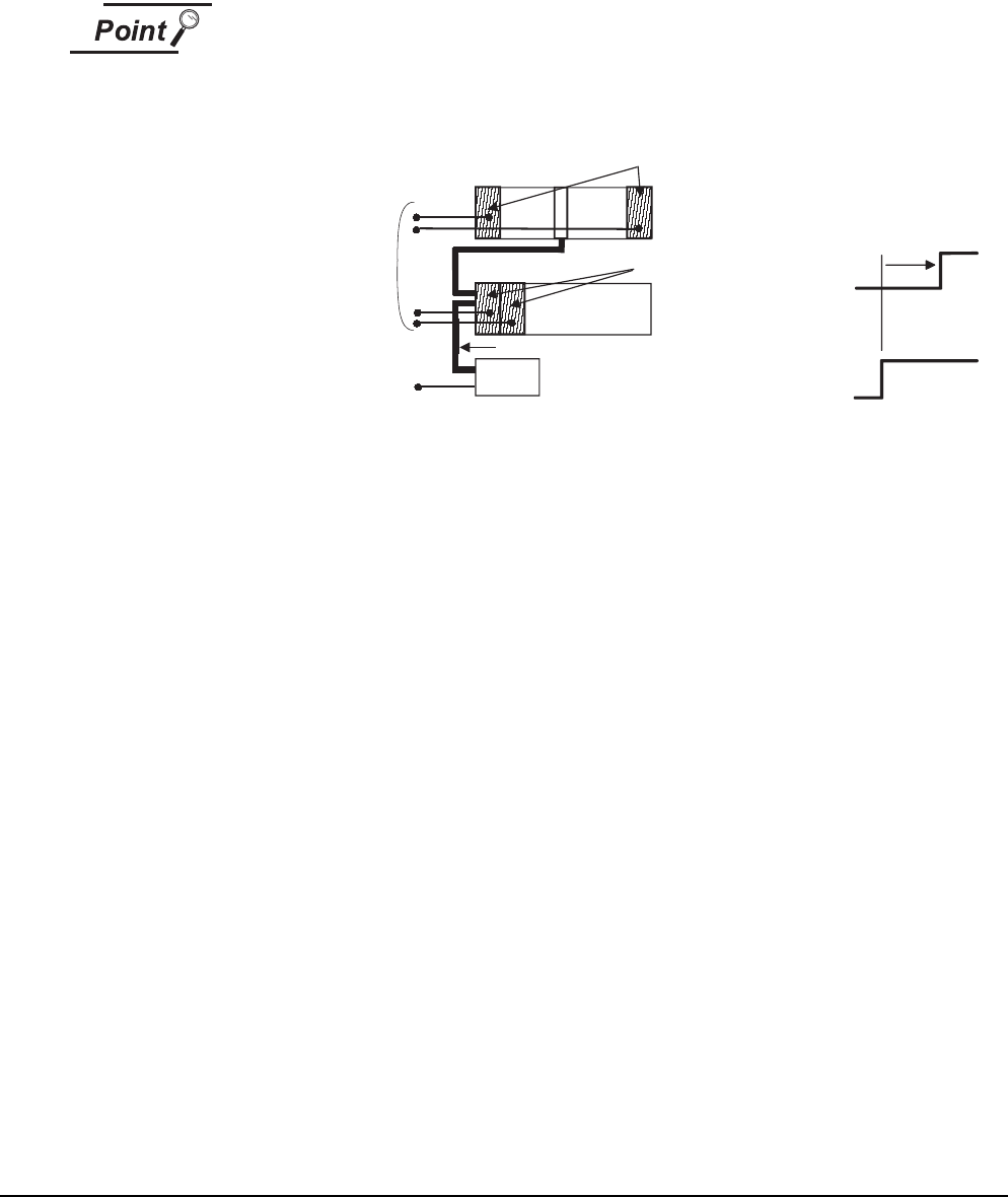
Power on the GOT-A900 series and Q4ARCPU duplex system in the following order.
(1) Power on the GOT-A900 series.
(2) 1 to 2 seconds after power-on of the GOT-A900 series, power on the Q4ARCPU
duplex system.
It is recommended to switch power on with an external circuit configured.
If power is not switched on in the order as specified in the restriction, the Q4ARCPU
duplex system will not start up in system A but will start up in system B before it starts
control.
1 to 2s
OFF
OFF
ON
ON
A61RP
GOT
Power supply
of GOT-A900 series
Power supply
of Q4ARCPU
duplex system
A61RP
Bus connection cable
Main base
Extension base
Power supply
of GOT-A900 series
Power supply
of Q4ARCPU
duplex system