


4 - 1
1
OVERVIEW
2
SYSTEM
CONFIGURATION
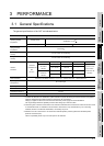
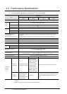
3
PERFORMANCE
4
NAMES OF
THE PARTS AND
THEIR SETTINGS
5
ROUGH
PRE-OPERATION
PROCEDURE
6
HANDLING
7
MAINTENANCE AND
INSPECTION
8
EMC DIRECTIVE
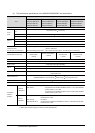
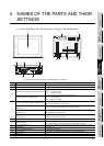
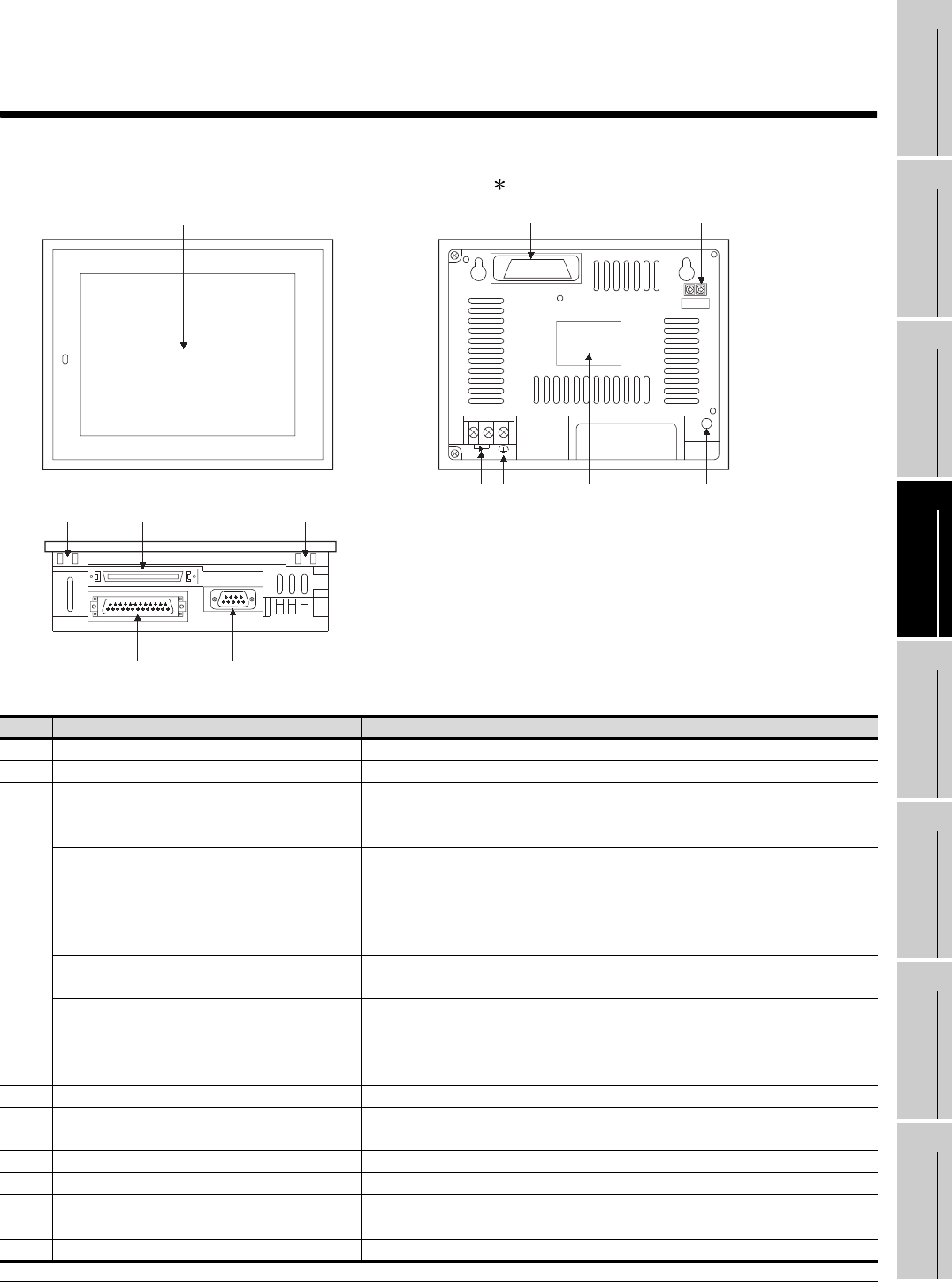
4 NAMES OF THE PARTS AND THEIR
SETTINGS
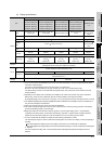
(1) Names of the Parts and Their Settings of the A95 GOT are indicated below.
*1: The shape of the interface section changes depending on the GOT.
No. Name Description
1) Display section Shows the screen
2) Reset button Used to reset the hardware of the GOT (invalid for bus connection)
3)
Extension number setting switch, (A951GOT only)
Used to set the extension number for GOT assignment
1 to 7 : Extension number
8, 9, 0 : Must not be used
I/O slot setting switch (A951GOT only)
Used to set the I/O slot number for GOT assignment
0 to 7 : I/O slot number
8, 9 : Must not be used
4)
RS-422 communication interface (A950GOT only)
For RS-422 communication connection
(D-sub 25-pin female metric screw type)
Bus communication interface for QCPU (Q mode)
(A951GOT only)
For bus connection cable connection (For QCPU (Q mode))
Bus communication interface
(A951GOT only)
For bus communication cable connection
(For A/QnA/Motion controller CPU)
RS-232C communication interface
(A953GOT only)
For RS-232C communication cable connection
(D-sub 9-pin male inch screw type)
5) Communication module interface (A956GOT only) Interface for loading the communication module
6) RS-232C interface
For connection of personal computer
For connecting the bar code reader (D-sub 9-pin male inch screw type)
7) Option module interface For connection Printer I/F module, Memory card I/F module, External I/O module
8) Terminal block For power input
9) Mounting fixture fitting portion For mounting fixture fitting
10) Ground terminal For earthling (For safety, please make sure to ground this terminal.)
11) Rating plate ---
POWER
1) 5) 3)
8) 2)
11)10)
9) 7) 9)
4) *1 6)