


4 - 2
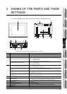
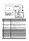
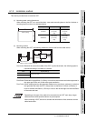
(2) Names of the Parts and Their Settings of the A956WGOT are indicated below.
No. Name Description
1) Display section Shows the screen
2) Reset button Used to reset the hardware of the GOT (invalid for bus connection)
3) Compact flash PC card access switch
Used to set the condition of access to the compact flash PC card when it is loaded during
power-on (Factory-set to OFF)
OFF :Access from GOT to compact flash PC card inhibited
ON :Access from GOT to compact flash PC card enabled
(When a memory card interface unit is used, a compact flash PC card cannot be used. There-
fore, turn this switch OFF.)
4) Compact flash PC card LED
Indicates whether the compact flash PC card may be loaded/unloaded or not
OFF :Compact flash PC card may be loaded/unloaded
(When switch 3 is OFF)
ON :Compact flash PC card must not be loaded/unloaded
(When switch 3 is ON)
5) RS-232C interface
For connection of personal computer
For connecting the bar code reader
6) Communication module interface Interface for communication module loading
7) Compact flash card slot Slot for Compact flash PC card loading
8) Option module interface For connection Printer I/F module, Memory card I/F module, External I/O module
9) Slot cover Cover of the memory board slot and the communication board slot
10) Memory board slot Slot for memory board loading
11) Communication board slot Slot for communication board loading
12) Terminal block For power input
13) Mounting fixture fitting portion For mounting fixture fitting
14) Ground terminal For earthing (For safety, please make sure to ground this terminal.)
15)
Bus connection board setting switch confir-
mation hole
For confirming the extension number of the I/O slot number set with the bus connection board
(If you are not using the A9GT-50WBUSS, it is possible to attach the seal included with the
GOT main unit to cover the hole.)
14)
1)
2)
3)
4)
5)
6)
7)
13)
12)
11)
10)
9)
8)
15)
13)