


Page 24 MAXX-2400HD Owner’s Manual
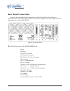
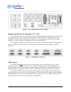
Rear Panel Connections
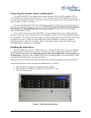
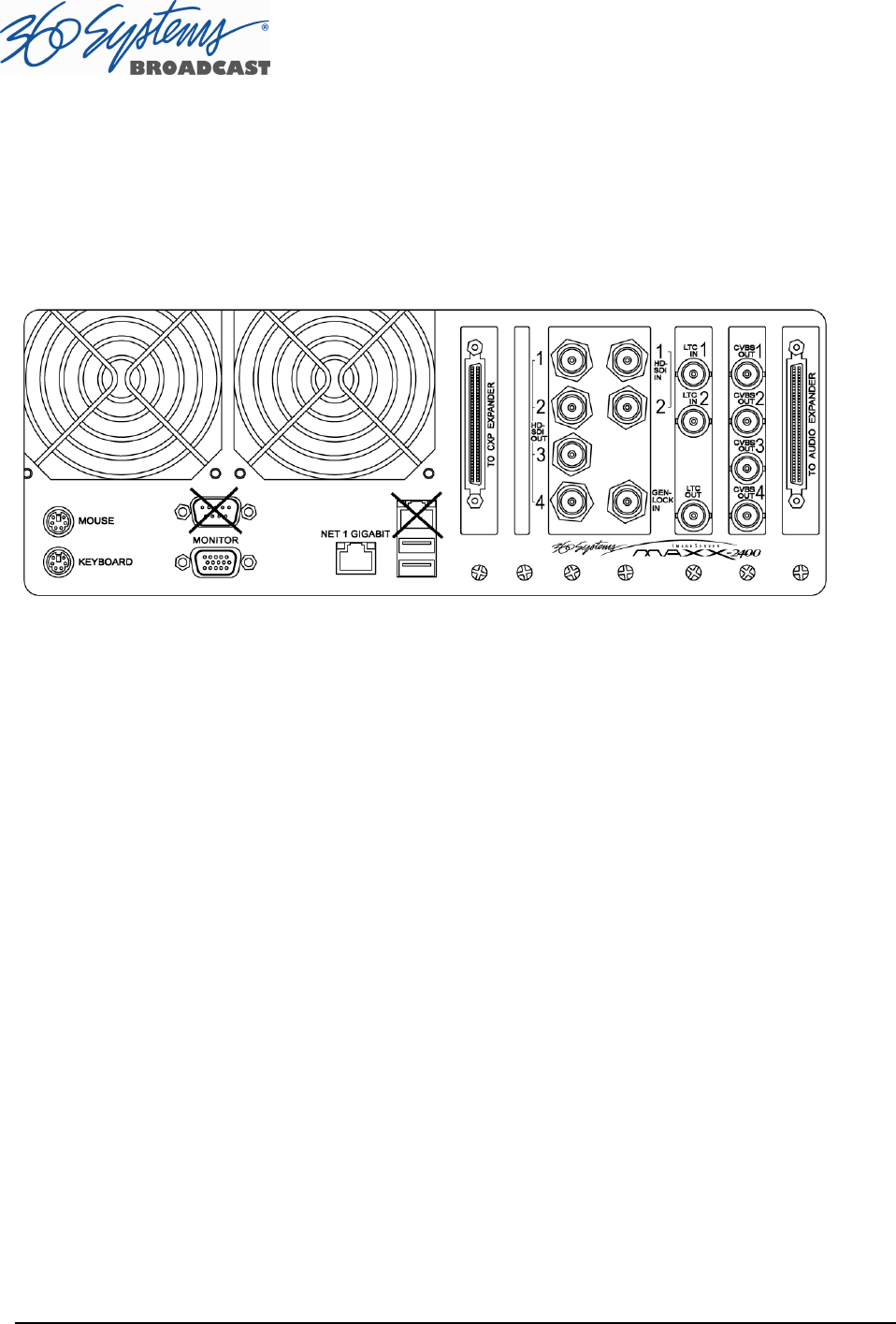
Figure 2 indicates the Rear Panel connections on MAXX-2400HD. Each connection is
described briefly in the following text. Make all connections appropriate to other equipment before
applying power to the MAXX-2400HD.
Figure 2 - Rear Panel Detail
Rear Panel Connections to the MAXX-2400HD Server
Mouse
Keyboard
USB (do not connect)
CXP Interface Connector
RS-232 Serial Port (do not connect)
VGA Monitor
NET 1 - Gigabit Ethernet
NET 2 - not used
Channel 1 and 2 HD-SDI Inputs (bi-directional)
Channel 1, 2, 3, 4 HD-SDI outputs
Channel 1, 2, 3, 4 - CVBS monitoring outputs
Channel 1 LTC Input
Channel 2 LTC Input
LTC Output
Genlock Input
Audio Module Connector (AXP or DXP)