


17
Nº512 CD/SACD™ Player
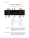
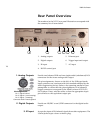
4. RS-232 Control port
Provides serial control through a standard RS-232 connection. Refer
to the separate document, Nº512 Serial Protocol Definitions, for
further details.
5. Ethernet port
Used to support external or ML Net control over a standard
Ethernet network. For information on how to set up and use the
Ethernet port, refer to the “Network Setup” and “ML Net” sections
found later in this manual.
6. Trigger Input and
Output
Used to activate other components in the home entertainment
system, such as amplifiers, lights, window shades, and video
screens. The rear panel of the Nº512 has two trigger connectors –
one input and one output. The trigger input can receive a 12V DC
signal from a connected component. The trigger input passes
through to the trigger output signal, enabling a daisy-chain of
devices to be controlled by a single trigger signal.
Receiving a trigger signal causes the Nº512 to change its power state.
If the Nº512 is in Standby mode, it is powered on when a 12V DC
signal is received on the trigger input. Conversely, if the Nº512 is
powered on, then 0V DC on the trigger signal puts the Nº512 into
Standby mode.
The Trigger Output goes to 12V DC when the Nº512 is powered on
and goes to 0V DC when the Nº512 is placed into Standby mode or
powered off.
7. AC Input
Provides AC power to the Nº512 when the supplied power cord is
connected from the AC input connector on the Nº512 rear panel to
an electrical outlet.
Caution! Before operating the N
o
512, verify that the voltage label near the
AC input connector indicates an operating voltage compatible
with the voltage level of the electrical outlet you intend to use.