16
Mark Levinson
Rear Panel Overview
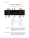
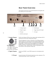
The numbers in the Nº512 rear panel illustration correspond with
the summary list of items below.
1. Analog outputs
2. Digital outputs
3. IR input
4. RS-232 control port
5. Ethernet port
6. Trigger input and output
7. AC input
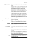
1. Analog Outputs
Provide two balanced XLR and two single-ended (unbalanced) RCA
connectors for the stereo analog audio output.
The pin assignments, shown on the left, of the XLR-type female
input connector are consistent with the standards adopted by the
Audio Engineering Society. Refer to the operating manual of your
preamplifier to ensure that the pin assignments of its balanced
output connectors correspond to the Mark Levinson Nº512 CD/
SACD player. If not, wire the cables so that the appropriate input
pin connects to the equivalent output pin.
2. Digital Outputs
Provide an AES/EBU or an S/PDIF connector for the digital audio
output.
3. IR Input
Accepts the input of IR (infrared) signals from other equipment. The
3.5mm jack accepts a stereo or mono plug.
1
2
3 4
5 6
7
Pin Assignments:
Pin 1: Signal Ground
Pin 2: Signal + (non-inverting)
Pin 3: Signal – (inverting)
Connector shell is chassis ground


