Basic Operation
Lexicon
2-10
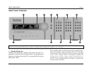
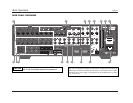
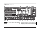
Rear Panel Overview (continued from page 2-9)
Note:
The numbered items below correspond with the rear
panel illustrations on pages 2-6 and 2-8.
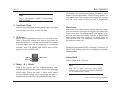
13.Trigger Output Connectors
Provide 12V DC output to control connected components.
Three trigger output connectors are available on a removable
terminal block. The connector labeled PWR – the power trigger
output connector – is not configurable. It is activated when the
MC-12 is activated, and deactivated when the MC-12 is
deactivated. The trigger output connectors labeled 1 and 2 can
be configured for remote or program operation.
14.IR IN Connector
Accepts input of IR signals from infrared distribution equipment.
One 3.5mm jack that accepts a stereo plug (Tip/Ring connection)
or mono plug (Tip/Sleeve connection) is available.
15.Microphone Input Connectors
Provide microphone input for speaker distance and output
level calibration. Four 3.5mm Tip/Ring/Sleeve connectors are
available.
16.Removable Access Panel
Accommodates connectors for emerging technologies.
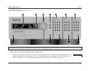
REMOTE CONTROL OVERVIEW
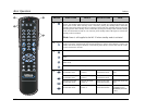
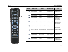
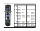
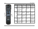
The MC-12 remote control provides full operation of the MC-12,
performing commands such as menu navigation that are not
available from the front panel. The command matrix that begins
on page 2-14 indicates the commands remote control buttons
perform when each command bank is activated. The numbered
items in the matrix correspond with the remote control illustrations
on pages 2-14 to 2-18.
OPERATION CONSIDERATIONS
The bulleted items that begin below describe factors that can
improve or impede remote control operation. It is recommended
to observe these items as well as the battery installation instructions
on page 1-5 before operating the remote control.
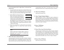
Please note the following before operating the MC-12 remote
control:
• When the MC-12 is not using the rear panel IR IN connector,
the remote control must be in line-of-sight with the front panel
IR receiver for proper operation. Eliminate obstructions
between the remote control and the IR receiver. The remote
control might become unreliable if strong sunlight or
fluorescent light is shining on the IR receiver.
• For optimal performance, position the remote control at a 30
degree angle no more than 17 feet (5m) from the MC-12. If
the MC-12 is placed inside a glass cabinet, smoked glass will
reduce the remote control range.
• Remote controllers for different components can interfere with
one another. It is recommended to avoid using remote controls
for different components at the same time.
• The remote control batteries should be replaced as needed.


