


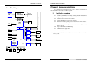
CHAPTER 2 –Hardware Installations
SYS7180VE User’s Manual
21
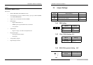
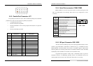
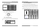
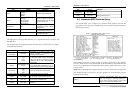
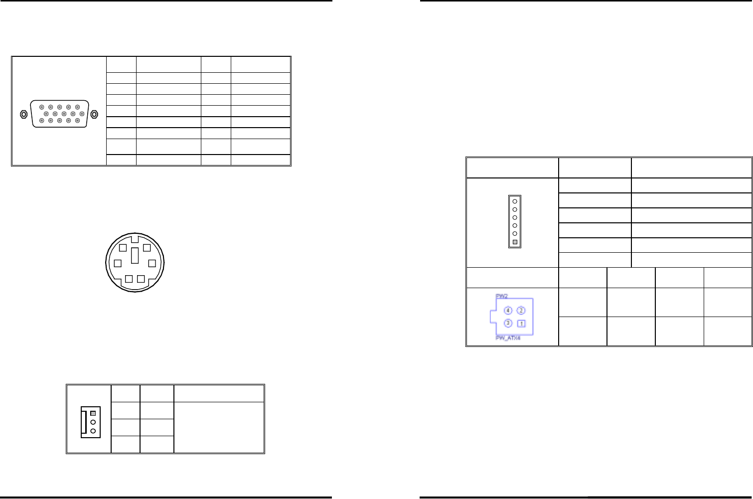
2.5.10 VGA Connector:
It is a VGA CRT connector. The pin assignments are as follows:
PIN No.
Function PIN No.
Function
1 Red 2 Green
3 Blue 4 N.C
5 GND 6 GND
7 GND 8 GND
9 VCC 10 GND
11 N.C 12 DDC data
13 H-Sync 14 V-Sync
6
15
10
15 11
15 DDC clock 16 N.C
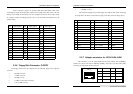
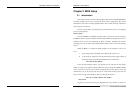
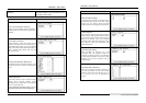
2.5.11 Keyboard / Mouse Connector:
5
1
2
3
6
4
Keyboard Clock
GND
Keyboard Data
Mouse Data
VCC
Mouse Clock
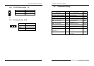
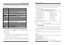
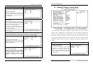
2.5.12 CPU FAN Connector:
FAN is a 3-pins box-header for the CPU cooling fan power connector. The fan
must be a 12V fan. Pin 3 is for Fan speed sensor input. Pin 2 is for PWM regulating voltage
output.
PIN No.
Function
Connector type for Cable
1 GND
2 POWER
FAN1
1
2
3
3 FAN
Housing: 5102-03 (molex)
Contact: 5103 (molex)
CHAPTER 2 –Hardware Installations
22
SYS7180VE User’s Manual
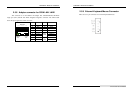
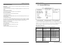
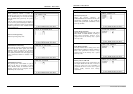
2.5.13 ACPI Connector: J2
When used with an ATX-compliant power supply that supports remote power
on/off, the CPU card can turn off the system power through software control.
To enable soft-off control in software, advanced power management must be
enabled in the Setup program and in the operation system. When the system BIOS receives
the correct APM command from the operating system, the BIOS turns off power to the
computer.
With soft off enabled, if power to the computer is interrupted by a power outage or
a disconnected power cord, when power resumes, the computer returns to the power state it
was in before power was interrupted (on or off).
J2
PIN No. Function
1 5VSB
2 PS_ON
3 GND
4 PWRCTL
5 GND
J2
6
5
4
3
2
1
6 SLEEPSW
PW2
PIN No. Function PIN No. Function
4 +12V 2 GND
3 +12V 1 GND