


CHAPTER 2 –Hardware Installations
SYS7180VE User’s Manual
15
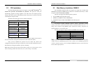
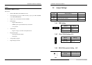
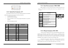
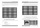
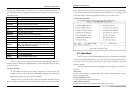
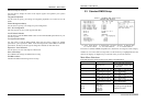
2.5.3 Parallel Port Connector: LPT
The parallel port bracket can used to add an additional parallel port for additional
parallel devices. There are four options for parallel port operation:
Compatible (Standard mode)
Bi-Directional (PS/2 compatible)
Bi-Directional EPP. A driver from the peripheral manufacturer is required for
operation.
Bi-Directional High-speed ECP
Pin Description Pin Description
1
Strobe#
14
Auto Form Feed#
2
Data 0
15
Error#
3
Data 1
16
Initialize#
4
Data 2
17
Printer Select In#
5
Data 3
18
GND
6
Data 4
19
GND
7
Data 5
20
GND
8
Data 6
21
GND
9
Data 7
22
GND
10
Acknowledge#
23
GND
11
Busy
24
GND
12
Paper Empty#
25
GND
13
Printer Select
26
CHAPTER 2 –Hardware Installations
16
SYS7180VE User’s Manual
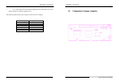
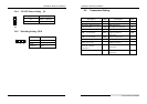
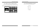
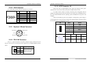
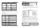
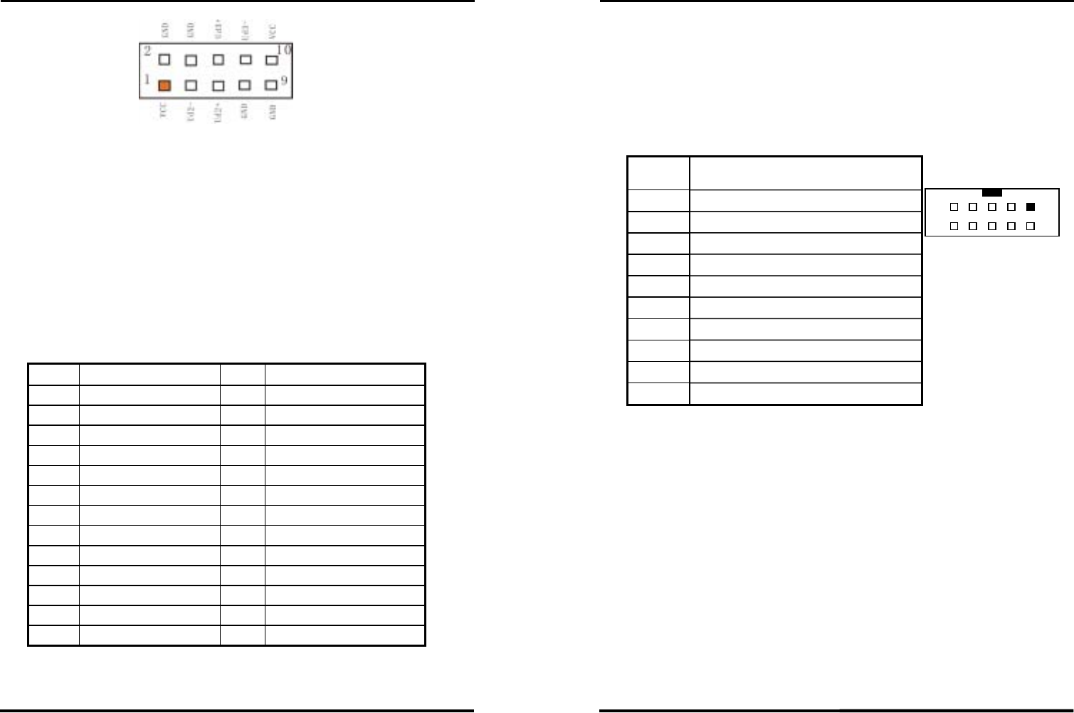
2.5.4 Serial Port connector: COM1/COM2
COM1, COM2 are use in the 10-pins box-header, are onboard serial ports of the
CPU card SYS7180VE. The following table shows the pin assignments of these
connectors.
COM1/2
Pin
Description
1
Data Carrier Detect (DCD)
2
Data Set Ready (DSR)
3
Receive Data (RXD)
4
Request to Send (RTS)
5
Transmit Data (TXD)
6
Clear to Send (CTS)
7
Data Terminal Ready (DTR)
8
Ring Indicator (RI)
9
Ground (GND)
10
GND
9 1
10 2
COM1 / COM2
2.5.5 IDE port Connector: IDE1/ IDE2
The CPU card SYS7180VE provides a bus-mastering PCI IDE interfaces. These
interfaces support PIO Mode 3, PIO Mode 4, ATAPI devices (e.g., CD-ROM), and Ultra
DMA/33/66/100 synchronous-DMA mode transfers. The BIOS supports logical block
addressing (LBA) and extended cylinder head sector (ECHS) translation modes. The BIOS
automatically detects the IDE device transfer rate and translation mode.
Programmed I/O operations usually require a substantial amount of processor
bandwidth. However, in multitasking operating systems, the bandwidth freed by bus
mastering IDE can be devoted to other tasks while disk transfers are occurring.