


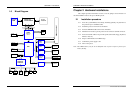
CHAPTER 2 –Hardware Installations
SYS7180VE User’s Manual
13
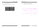
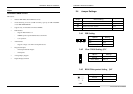
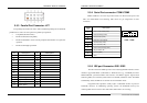
2.5.1 Front Panel Connector: J1
This header can be connected to a front panel power switch. The front panel
connector includes headers for these I/O connections:
Power switch
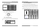
Power LED
This header can be connected to an LED that will light when the computer is
powered on.
Hard drive activity LED
This header can be connected to an LED to provide a visual indicator that data is
being read from or written to an IDE hard drive. For the LED to function properly, the IDE
drive must be connected to the onboard IDE controller.
Speaker
A speaker can be installed on the SYS7180VE as a manufacturing option. The
speaker is enabled by a jumper on pins 2, 4, 6, 8 of the front panel connector. Removing
the jumper can disable the onboard speaker, and an offboard speaker can be connected in
its place. The speaker (onboard or offboard) provides error beep code information during
the POST in the event that the computer cannot use the video interface. The speaker is not
connected to the audio subsystem and does not receive output from the audio subsystem.
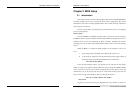
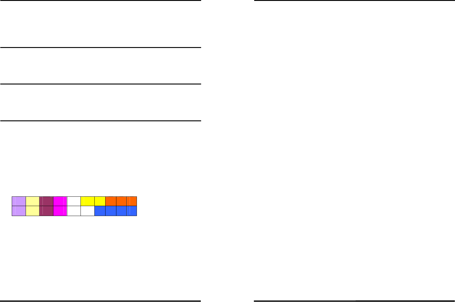
19 17 15 13 11 9 7 5 3 1
20 18 16 14 12 10 8 6 4 2
1-3-5: POWER LED 2-4-6-8: SPEAKER 7-9: KEYLOCK
13-14:POWER ON 15-16: GREEN LED 17-18: RESET
19-20: IDE LED
PIN1 POWER LED+ PIN5 POWER LED-
PIN15 GREEN LED+ PIN16 GREEN LED-
PIN19 IDE LED- PIN20 IDE LED+
CHAPTER 2 –Hardware Installations
14
SYS7180VE User’s Manual
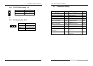
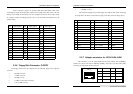
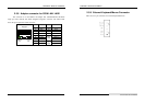
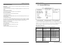
2.5.2 USB Connector: USB1-2 USB3-4
Note: USB cable is special designed for SYS7180VE
The Universal Serial Bus (USB) that allows plug and play computer peripherals
such as keyboard, mouse, joystick, scanner, printer, modem/ISDN, CD-ROM and floppy
disk drive to be automatically detected when they are attached physically without having to
install drivers or reboot.
The USB connectors allow any of several USB devices to be attached to the
computer. Typically, the device driver for USB devices is managed by the operating
system. However, because keyboard and mouse support may be needed in the Setup
program before the operating system boots, the BIOS supports USB keyboards and mice.
The CPU card has four USB ports; one USB peripheral can be connected to each
port. For more than four USB devices, an external hub can be connected to either port. The
four USB ports are implemented with stacked back panel connectors. The CPU card fully
supports the universal host controller interface (UHCI) and uses UHCI-compatible
software drivers.
USB features includes:
Self-identifying peripherals that can be plugged in while the computer is running
Automatic mapping of function to driver and configuration
Support for synchronous and asynchronous transfer types over the same set of wires
Support for up to 127 physical devices
Guaranteed bandwidth and low latencies appropriate for telephony, audio and other
applications
Error-handling and fault-recovery mechanisms built into the protocol