


28 Intel Blade Server Fibre Channel Switch Module SBCEFCSW / FC Expansion Card SBFCM Guide
threshold
Initiates a configuration session by which to generate and log alarms for selected events. Each event,
its thresholds, and sampling interval is displayed, one line at a time and you are prompted for a value.
For each parameter, enter a new value or press the Enter key to accept the current value shown in
brackets. These parameters must be saved in a configuration and activated before they will take effect.
See the “Config command” on page 10 for information about saving and activating a configuration.
Table 9 describes the Set Config threshold parameters.
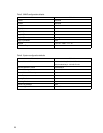
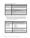
SymbolicName Descriptive name.
R_T_TOV Receiver Transmitter Timeout Value. Specifies the number of milliseconds a
port is to wait to receive a response from another port. The default is 100.
R_A_TOV Resource Allocation Timeout Value. The number of milliseconds the switch
waits to allow two ports to allocate enough resources to establish a link. The
default is 10000.
E_D_TOV Error Detect Timeout Value. The number of milliseconds a port is to wait for
errors to clear. The default is 2000 msec.
FS_TOV Fabric Stability Timeout Value. The default is 5000 msec.
DS_TOV Distributed Services Timeout Value (Management Server, Name Server).
The default is 5000 msec.
PrincipalPriority The priority used in the FC-SW-2 principal switch selection algorithm. 1 is
high, 255 is low.
ConfigDescription The name for the configuration. The default is undefined.
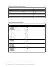
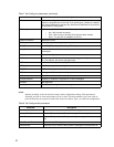
Table 9. Set Config threshold parameters
Parameter Description
Threshold Monitoring Enabled Master enable/disable parameter for all events. Enables (True) or
disables (False) the generation of all enabled event alarms.
CRCErrorsMonitoringEnabled
DecodeErrorsMonitoringEnabled
ISLMonitoringEnabled
LoginMonitoringEnabled
LogoutMonitoringEnabled
LOSMonitoringEnabled
The event type enable/disable parameter. Enables (True) or disables
(False) the generation of alarms for each of the following events:
• CRC errors
• Decode errors
• ISL connection count
• Login errors
• Logout errors
• Loss-of-signal errors
Rising Trigger The event count above which an event is logged. Once the count
exceeds the rising threshold, one alarm is logged. The switch will not
generate another alarm for that event until the count falls below the
falling threshold and rises again above the rising threshold.
Falling Trigger The event count above which an event becomes eligible for logging in
the alarm log.
Sample Window The period of time in seconds in which to count events.
Table 8. Set Config switch parameters (continued)
Parameter Description