


114 Intel Blade Server Fibre Channel Switch Module SBCEFCSW / FC Expansion Card SBFCM Guide
To run an internal, external, or online port loopback test on an external port, see “Port testing” on page 117.
Switch management utility functions
This chapter contains information about the following topics:
• LED diagnostics
• Port testing
• Fibre Channel switch module monitoring using SNMP
• Restoring Fibre Channel switch module configuration defaults
• Using the Fabric View application
LED diagnostics
The Fibre Channel switch module performs a POST as part of its power-on procedure. The POST diagnostic
program performs the following tests:
• Checksum tests on the boot firmware in PROM and the switch module firmware in flash memory
Internal data loopback test on all ports
• Access and integrity test on the switch module ASIC
During the POST, the switch module logs any errors encountered. Some POST errors are fatal; others are non-
fatal. The switch module uses the heartbeat LED and the logged-in LED to indicate switch and port status. A
fatal error disables the switch module so that it will not operate. If a non-fatal error occurs, the switch module
can still operate but disables the ports that have errors. Regardless of whether the problem is fatal or nonfatal,
contact your Intel technical support representative.
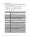
If there are no POST errors, the heartbeat LED flashes at a steady rate of once per second. If a fatal error
occurs, the heartbeat LED will show an error flash pattern. If there are non-fatal errors, the switch module
disables the failed ports and flashes the associated logged-in LEDs. See “Heartbeat LED patterns” on page 115
for more information about heartbeat LED flash patterns.
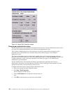
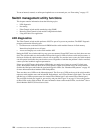
There are three sets of LEDs on the information panel. The first row of LEDs at the top of the switch module
represent switch module status and include OK, ♥ (heartbeat), and ! (Fibre Channel switch fault). The second
and third sets of LEDs represent status for external Fibre Channel port 2 and external Fibre Channel port 1.
The port LEDs include port logged-in, port activity, and port fault. Figure 21 on page 115 shows the location
of these LEDs on the switch module. For more information about switch module LEDs, see the Intel
®
Server
Switch Module SBCEFCSW Installation Guide.