19
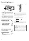
Connections
PRE
FRONT
SUB
SURR
R
GND
FRONT
SUB
SURR
SURR
BACK
R
DIGITAL
OUTPUT
2
3
1
2
3
1
OPT
DIGITAL
INPUT
OPT
COAX
DIGITAL
INPUT
SURR
BACK
TENNA
DIO
L
PH
CD
OUT
IN
TAPE
L
AUDIO
VIDEO
S VIDEO
MONITOR
OUT
R
L
OUT
IN
OUT
IN
OUT
IN
IN
IN
ZONE 2
DVD
VIDEO 1
VIDEO 2
VIDEO 3
VIDEO 4
DIO
AUDIO
VIDEO
S VIDEO
COMPONENT
VIDEO
Y
P
B
PR
OUTPUT
INPUT 1
Y
P
B
PR
INPUT 2
Y
P
B
PR
AM
FM
75
R
L
PR
PB
Y
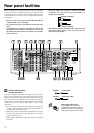
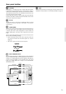
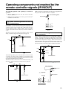
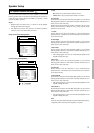
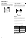
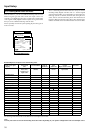
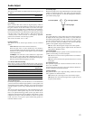
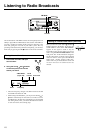
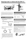
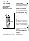
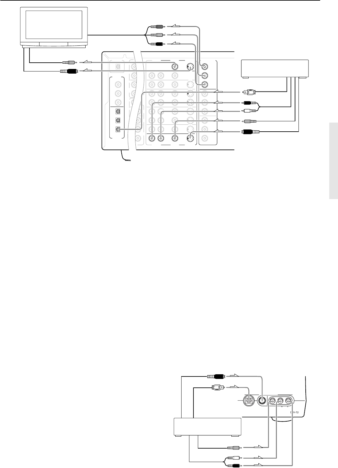
9. TV monitor or projector
(MONITOR OUT)
L (white)
R (red)
Digital audio output
(optical)
Video input
S Video input
Component video input
Video output
S Video output
Analog audio
output
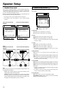
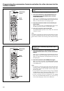
8. Satellite tuner or television
(VIDEO 4)
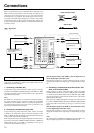
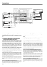
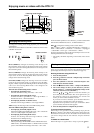
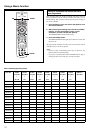
7, 8. Connecting a satellite tuner, television, or settop
box (VIDEO 3 or 4)
If the satellite tuner or television is equipped with an S video output
terminal, connect it to the S VIDEO 3 (or 4) IN terminal with an S
video cable. If it does not have an S video output terminal, connect
its video output terminal to the VIDEO 3 (or 4) IN terminal using an
RCA-type video connection cable. You do not need to connect to
both the S VIDEO 3 (or 4) IN and VIDEO 3 (or 4) IN terminals. If
the satellite tuner or television has component video outputs,
connect them to one of the COMPONENT VIDEO INPUT jacks.
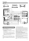
With the initial settings of the DTR-7.2, the VIDEO 3 and
VIDEO 4 input sources are set for the COMPONENT VIDEO
INPUT 2 jack.
If the video connection is made at COMPONENT VIDEO INPUT
1, this must be changed at the Setup menu: Input Setup → Video
Setup → Component Video (see page 36).
Using an RCA-type audio connection cable, connect the audio
output terminal on the satellite tuner or television to the same
VIDEO 3 (or 4) IN audio jacks on the DTR-7.2. Make sure that you
properly connect the left channel to the L jack and the right channel
to the R jack.
If the device has a digital output jack as well, be sure to also connect
it to either a DIGITAL INPUT (COAX) or DIGITAL INPUT (OPT)
jack on the DTR-7.2 depending on the device.
With the initial settings of the DTR-7.2, the VIDEO 3 input source is
set for digital input at the OPT 3 jack.
If the digital connection is made at a different jack, this must be changed
at the Setup menu: Input Setup → Digital Setup (see page 34).
With the initial settings of the DTR-7.2, nothing is allocated as
the digital input source for VIDEO 4 (----).
If you connect a digital component to the VIDEO 4 terminal, be sure
to make the appropriate settings in the Digital Setup sub-menu (see
page 34).
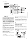
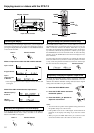
9. Connecting a television monitor or projector
(MONITOR OUT)
The DTR-7.2 is equipped with a simple Y/C separate circuit and
simple Y/C mixed circuit. Since both the signal from the S VIDEO
and VIDEO inputs are output to the MONITOR OUT S VIDEO
output, if the television or projector is equipped with an S video
input, it is unnecessary to connect the video connectors. If it is
equipped with only a video input, connect it to the MONITOR OUT
VIDEO output.
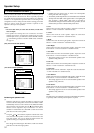
If the monitor or projector is equipped with an S video output
terminal, connect it to the MONITOR OUT S VIDEO terminal with
an S video cable. If it does not have an S video output terminal,
connect its video output terminal to the MONITOR OUT VIDEO
terminal using an RCA-type video connection cable. You do not
need to connect to both the MONITOR OUT S VIDEO and
MONITOR OUT VIDEO terminals. If the device has component
video inputs, connect them to the COMPONENT VIDEO OUTPUT
jacks.
Note:
Note that the Setup menu will only be displayed on the monitor
connected to MONITOR OUT and not those connected to the
COMPONENT VIDEO OUTPUT jacks.
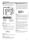
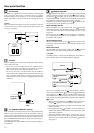
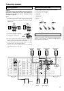
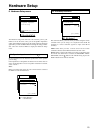
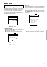
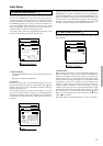
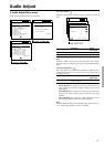
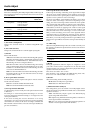
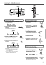
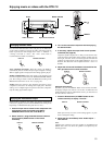
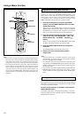
10. Connecting video camera, etc.
(Video 5/Video Cam Input)
If the device is equipped with an S video output terminal, connect it
to the S Video 5 input terminal with an S video cable. If it does not
have an S video output terminal, connect its video output terminal to
the Video 5 input terminal using an RCA-type video connection
cable. You do not need to connect to both the S Video 5 input and
Video 5 input terminals.
The Video 5 digital input is fixed to the Digital input on the front
panel.
Digital
Video 5
/
Video Cam Input
S Video
Audio
Video L R
Video output
Analog output
Right (red)
Left (white)
Digital output
(optical)
10. Video camera/Video game
(VIDEO 5/VIDEO CAM INPUT)
S Video output