


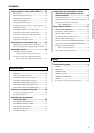
13
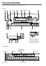
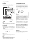
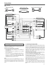
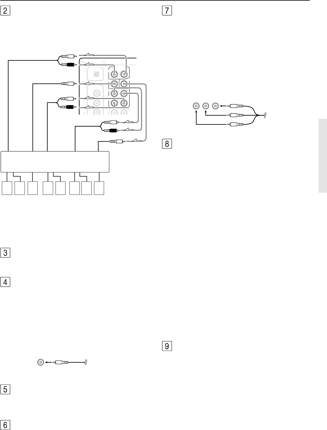
PRE OUT
FRONT
SUB
SURR
CENTER
R
L
SURR
BACK/
MULTI
C
INPUT
FRONT
2
3
1
DIGITAL
OUTPUT
OPT
COAX
DIGITAL
INPUT
Front input
Surround input
Surround
back
Center
Subwoofer
R (red)
L (white)
R (red)
L (white)
R (red)
L (white)
87654321
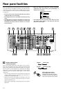
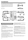
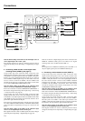
Rear panel facilities
Power amplifier
1. Front left speaker
2. Front right speaker
3. Subwoofer
4. Surround back left
speaker
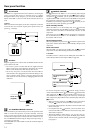
MONITOR OUT
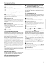
The monitor output includes both composite video and S video
configurations. This output is for connecting television monitors or
projectors.
ZONE 2 AUDIO/VIDEO OUT
Connect the device that will be used in the remote zone (Zone 2). For
more information regarding how to make the connections, refer to
“Connecting the remote zone (Zone 2) speakers” on page 24.
5. Surround back right
speaker
6. Surround left speaker
7. Surround right speaker
8. Center speaker
YPB PR RCA type
COMPONENT VIDEO INPUT/OUTPUT
If your DVD player or other device has component video
connectors, be sure to connect them to these component video
connectors on the DTR-7.2. The DTR-7.2 has two component video
input connectors to obtain the color information (Y, P
B, PR) directly
from the recorded DVD signal or other video component and one
component video output connector to output it directly into the
matrix decoder of the display device. By sending the pure DVD
component video signal directly, the DVD signal forgoes the extra
processing that normally would degrade the image. The result is
vastly increased image quality, with incredibly lifelike colors and
crisp detail.
RCA type
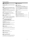
ANTENNA
These jacks are for connecting the FM indoor antenna and AM loop
antenna that are supplied with the DTR-7.2.
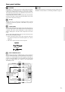
AUDIO IN/OUT
These are the analog audio inputs and outputs. There are eight audio
inputs and 3 audio outputs. The audio inputs and outputs require
RCA-type connectors.
• When connecting a VCR or other video component, make sure
you connect the audio and video leads together (i.e., both to
VIDEO 3).
• The PHONO (PH) input jacks on the DTR-7.2 is designed for
use with turntables that use moving magnet cartridges.
PRE OUT
These jacks are for connecting auxiliary power amplifier.
Using auxiliary power amplifiers allows you to listen at louder
volumes than with the DTR-7.2 alone. If power amplifiers are used,
connect each speaker to the corresponding power amplifier.
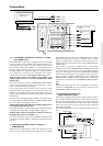
A-BUS
Congratulations for purchasing a most efficient, modern-day remote
controllable whole house audio system. A-BUS is a simple,
efficient, elegant audio distribution system. The wiring installation
time is significantly reduced as only a single CAT-5 wire is run to
each location. A-BUS is easy to use, reliable, affordable, and most of
all, far better sounding than conventional autoformer based volume
controls.
ZONE A/B/C/D: Use a CAT-5 (eight conductor twisted) cable to
connect directly from the receiver’s A-BUS RJ45 Hub to an A-BUS
keypad. A-BUS outputs enable connection up to four A-BUS
keypads.
Warning:
DO NOT connect A-BUS outputs to any computer or network
connections (i.e. ethernet). It will cause damage to the computer or
network components as 24-volt power runs on this same cable to
power the amplifier stages of the amplifier module.
IR control: Another feature of the A-BUS system is the ability to
control source equipment in another room where the A-BUS module
is installed. If you wish to control another source from the receiver at
the A-BUS keypad by remote control, connect A-BUS or another
brands’ IR emitter on the receiver’s 40 K terminal. Then place the
emitter on the remote receiver on the front panel.
Typically, the emitter will work when you connect with a 40 K
connector. If it does not work, try a 56 K connector.
DC INPUT: Connect A-BUS power supply. Do not use any other
AC Adapter on this connector as it may cause severe damage to the
receiver.
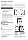
SPEAKERS
Six terminals are provided for the front left, front right, front center,
surround left, surround right, and surround back speakers. Speaker
outputs are compatible with banana plug connectors.