


12
DIGITAL
OUTPUT
PRE OUT
ANTENNA
DIGITAL
INPUT
OPT
COAX
2
3
1
2
3
FRONT
SUB
SURR
SURR
BACK
CENTER
R
L
AUDIO
R
L
PH
CD
OUT
IN
TAPE
R
L
AUDIO
VIDEO
S VIDEO
MONITOR
OUT
R
L
OUT
IN
OUT
IN
OUT
IN
IN
IN
ZONE 2
DVD
VIDEO 1
VIDEO 2
VIDEO 3
VIDEO 4
AUDIO
AUDIO
VIDEO
S VIDEO
COMPONENT
VIDEO
Y
P
B
P
R
OUTPUT
INPUT 1
Y
P
B
P
R
INPUT 2
Y
P
B
P
R
L
R
L
R
AC OUTLETS
AC 120
V 60
Hz
SWITCHED
TOTAL 120W 1A MAX.
I
R
IN
OUT
12V
TRIGGER
ZONE 2
REMOTE
CONTROL
1
OPT
GND
AM
4 OHMS MIN. OR
6 OHMS MIN.
/SPEAKER
SEE
INSTRUCTION
MANUAL FOR
CORRECT
SETTINGS.
CAUTION
:
SPEAKER
IMPEDANCE
A
B
A
B
I
R
OUT
40K
I
R
OUT
56K
DC IN
24V 4A
ZONE A
OUT
ZONE B
OUT
ZONE D
OUT
ZONE C
OUT
AV RECEIVER
MODEL NO.
DTR-7.2
AC
INLET
RS 232
FM
75
DIGITAL
INPUT
SURR
BACK
SPEAKER
FRONT SPEAKERS
SURR SPEAKERS
CENTER
SPEAKER
R
L
R
L
MULTI
CH
INPUT
FRONT
SUB
SURR
SURR
BACK
CENTER
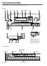
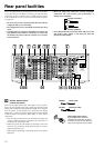
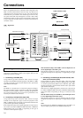
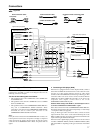
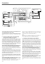
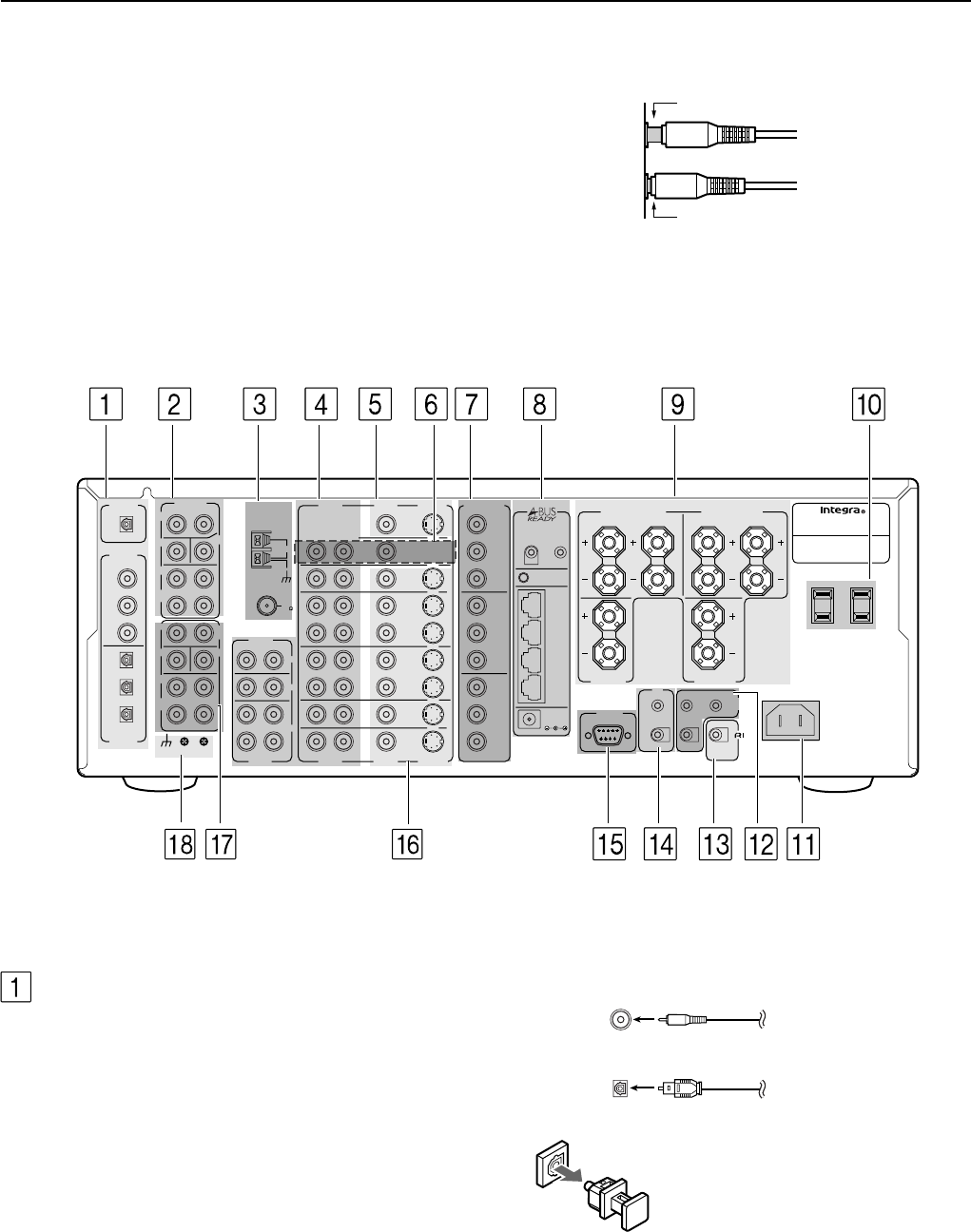
Rear panel facilities
Here is an explanation of the terminals found on the rear of the DTR-
7.2 and how they are used. Before connecting your audio and video
components, be sure to read this section carefully and then proceed
to the explanations on how to connect each individual component
(see page 16).
• Be sure to always refer to the instructions that came with the
component that you are connecting.
• Do not plug in the power cord until all connections have been
made.
• For input jacks, red connectors (marked R) are used for the
right channel, white connectors (marked L) are used for the
left channel, and yellow connectors (marked V) are used for
video connection.
• Do not bind audio/video connection cables with power cords
and speaker cables. Doing so may adversely affect the
picture and sound quality.
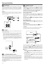
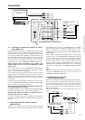
Improper connection
Inserted completely
• Insert all plugs and connectors securely. Improper
connections can result in noise, poor performance, or
damage to the equipment.
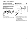
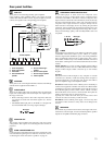
Optical digital input terminal
An optical digital input terminal is
equipped with a protection cap. When
connecting, remove this cap. When not
using, put the cap back on the terminal.
COAXIAL Coaxial cable
OPTICAL Optical fiber cable
DIGITAL INPUT/OUTPUT
(coaxial and optical)
These are the digital audio inputs and outputs on the rear panel.
There are three digital inputs with coaxial jacks and three with
optical jacks. The inputs accept digital audio signals from a compact
disc, LD, DVD, or other digital source component. For digital
output, there is 1 optical output. The digital outputs can be connected
to MD recorders, CD recorders, DAT decks, or other similar
components.
• Since an analog connection must be made when using Rec Out
or Zone 2, make sure that the connection to the input source is
not digital only, but analog as well.
• When using one of the optical input or output jacks, remove the
protective cap and keep it safely. When the jack is not used,
replace the protective cap.
• When using an optical input or output jack, always use an optical
fiber cable.