18
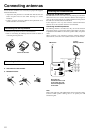
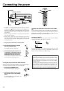
Connections
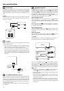
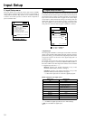
With the initial settings of the DTR-7.2, the DVD input source is
set for digital input at the COAX 1 jack.
If the digital connection is made at a different jack, this must be
changed at the Setup menu: Input Setup → Digital Setup (see page
34).
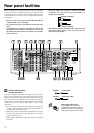
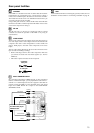
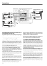
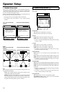
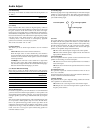
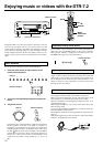
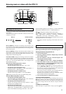
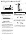
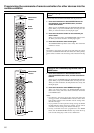
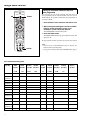
5. Connecting a DVD recorder or other digital video
recording device (VIDEO 2) (see page 17)
Using an RCA-type video connection cable, connect the video
output terminal (composite) on the device to the VIDEO 2 IN jacks
on the DTR-7.2 and video input terminal to the VIDEO 2 OUT jacks.
If there is an S video input/output terminal on the device, connect it
to the S VIDEO 2 IN/OUT jack using an S video cable. You do not
need to connect to both the S VIDEO 2 IN and VIDEO 2 IN
terminals. If the device has component video outputs, connect them
to one of the COMPONENT VIDEO INPUT jacks.
With the initial settings of the DTR-7.2, the VIDEO 2 input
source is set for the COMPONENT VIDEO INPUT 2 jack.
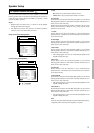
If the video connection is made at COMPONENT VIDEO INPUT 1,
this must be changed at the Setup menu: Input Setup → Video Setup
→ Component Video (see page 36).
Using an RCA-type audio connection cable, connect the audio
output terminal on the device to the same VIDEO 2 IN audio jacks
on the DTR-7.2 and audio input terminal to the VIDEO 2 OUT audio
jacks. Make sure that you properly connect the left channel to the L
jack and the right channel to the R jack.
If the device has a digital output jack as well, be sure to also connect
it to either a DIGITAL INPUT (COAX) or DIGITAL INPUT (OPT)
jack on the DTR-7.2 depending on the type of connector on the
device.
With the initial settings of the DTR-7.2, the VIDEO 2 input
source is set for digital input at the COAX 3 jack.
If the digital connection is made at a different jack, this must be changed
at the Setup menu: Input Setup → Digital Setup (see page 34).
If the device also has a digital input jack, it can be connected to the
DIGITAL OUTPUT (OPT) jack on the DTR-7.2 for digital
recording of the source for Rec Out at the DTR-7.2.
Note:
The output from the DIGITAL OUTPUT jack of the DTR-7.2 is
only the digital signal input to the DIGITAL INPUT jack.
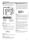
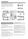
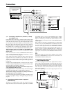
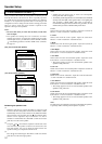
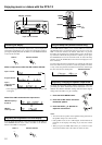
6. Connecting a video cassette recorder (VIDEO 1)
Using an RCA-type video connection cable, connect the video
output terminal (composite) on the video cassette recorder to the
VIDEO 1 IN jacks on the DTR-7.2 and video input terminal to the
VIDEO 1 OUT jacks. If there is an S video input/output terminal on
the video cassette recorder, connect it to the S VIDEO 1 IN/OUT
jack using an S video cable. You do not need to connect to both the
S VIDEO 1 IN and VIDEO 1 IN terminals. If the video cassette
recorder has component video outputs, connect them to one of the
COMPONENT VIDEO INPUT jacks.
With the initial settings of the DTR-7.2, the VIDEO 1 input
source is set for the COMPONENT VIDEO INPUT 2 jack.
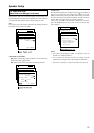
If the video connection is made at COMPONENT VIDEO INPUT 1,
this must be changed at the Setup menu: Input Setup → Video Setup
→ Component Video (see page 36).
Using an RCA-type audio connection cable, connect the audio
output terminal on the video cassette recorder to the same VIDEO 1
IN audio jacks on the DTR-7.2 and audio input terminal to the
VIDEO 1 OUT audio jacks. Make sure that you properly connect the
left channel to the L jack and the right channel to the R jack.
With the initial settings of the DTR-7.2, the VIDEO 1 input
source is set for digital input at the COAX 2 jack.
If the digital connection is made at a different jack, this must be
changed at the Setup menu: Input Setup → Digital Setup (see page
34).
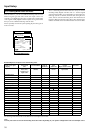
PRE
FRONT
SUB
SURR
R
GND
FRONT
SUB
SURR
SURR
BACK
R
DIGITAL
OUTPUT
2
3
1
2
3
1
OPT
DIGITAL
INPUT
OPT
COAX
DIGITAL
INPUT
SURR
BACK
TENNA
DIO
L
PH
CD
OUT
IN
TAPE
L
AUDIO
VIDEO
S VIDEO
MONITOR
OUT
R
L
OUT
IN
OUT
IN
OUT
IN
IN
IN
ZONE 2
DVD
VIDEO 1
VIDEO 2
VIDEO 3
VIDEO 4
DIO
AUDIO
VIDEO
S VIDEO
COMPONENT
VIDEO
Y
P
B
P
R
OUTPUT
INPUT 1
Y
P
B
P
R
INPUT 2
Y
P
B
P
R
AM
FM
75
R
L
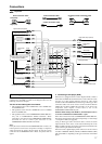
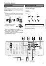
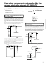
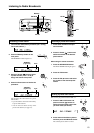
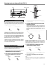
6. VCR (VIDEO 1)
7. Settop box, video camera
(VIDEO 3)
L (white)
R (red)
L (white)
R (red)
L (white)
R (red)
Digital audio output (optical)
Video input
S Video input
Analog audio
input
Video output
S Video output
Analog audio
output
Video output
S Video output
Analog audio
output