88
Zone 2—Continued
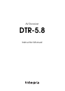
When the AV receiver’s 12 V TRIGGER OUT A/B/C
jack is connected to the 12 V trigger input on a connected
component, you can specify whether or not a 12-volt
trigger signal is output when that component is selected
as the source for the main room, Zone 2, or either.
Hookup
• Use a miniplug cable to connect the AV receiver’s 12
V TRIGGER OUT A, B, or C jack to the 12 V trigger
input on the connected component.
■ Delay
When several components are turned on simultaneously
via the 12-volt triggers, depending on the type of compo-
nents, a large amount of current may be drawn momen-
tarily. To prevent this, you can delay the trigger signals
output by the AV receiver. In addition, by delaying the
trigger signal for your power amplifier so that it’s the last
component to be turned on, you can avoid the “thump”
noise that’s sometimes heard when a source component
is turned on.
The delay setting determines how long after the input
source is changed on the AV receiver the trigger signal is
output. It can be set to 0 sec, 1 sec, 2 sec, or 3 sec. When
set to 0 sec, the trigger signal is output as soon as the
input source is changed.
■ 12V Trigger Setting for Each Input Source
By default, all input sources on the 12V Trigger A Setup
menu are set to Main, those on the 12V Trigger B Setup
menu are set to Main/Zone 2, and those on the 12V Trig-
ger C Setup menu are set to Zone 2.
Off: No trigger signal is output.
Main: Select this if you want to output a 12-volt trig-
ger signal when a connected component is
selected as the source for the main room.
Zone2: Select this if you want to output a 12-volt trig-
ger signal when a connected component is
selected as the source for Zone 2.
Main/Zone2: Select this if you want to output a 12-volt
trigger signal when a connected component is
selected as the source for either the main room
or Zone 2.
Using the 12V Triggers in Zone 2 and
the Main Room
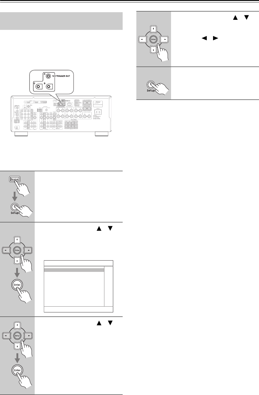
1
Press the [Receiver] button fol-
lowed by the [Setup] button.
The main menu appears onscreen.
2
Use the Up and Down [ ]/[ ]
buttons to select
“6. Miscellaneous,” and then
press [Enter].
The Miscellaneous menu appears.
3
Use the Up and Down [ ]/[ ]
buttons to select “12V Trigger
Setup” A, B, or C, and then press
[Enter].
6. Miscellaneous
1. Volume Setup
2. OSD Setup
3. 12V Trigger A Setup
4. 12V Trigger B Setup
5. 12V Trigger C Setup
4
Use the Up and Down [ ]/[ ]
buttons to select “Delay” or an
input source, and use the Left
and Right [ ]/[ ] buttons to
change the setting.
Repeat this step as necessary for each
setting.
5
Press the [Setup] button.
Setup closes.