


7
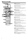
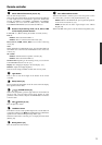
Using the remote controller
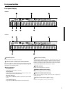
Point the remote controller toward the remote control sensor. The
STANDBY indicator lights up when the unit receives a signal from
the remote controller.
Notes:
• Make sure that the remote control sensor is not subject to strong
light such as direct sunlight or inverted fluorescent light for it
may prevent proper operation of the remote controller.
• Using another remote controller in the same room or using the
DTR-6.3/5.3 near equipment that uses infrared rays may cause
operational interference.
• Do not put objects on the remote controller. Its buttons may be
pressed by mistake and drain the batteries.
• Make sure the audio rack doors do not have colored glass.
Placing the DTR-6.3/5.3 behind such doors may prevent proper
remote controller operation.
• If there is any obstacle between the remote controller and the
remote control sensor, the remote controller will not operate.
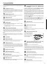
Installing the remote controller batteries
1. Remove the battery compartment cover by pressing it
and sliding it in the direction shown by the arrow
below.
2. Insert two AA (R6 or UM-3) batteries into the battery
compartment. Carefully follow the polarity diagram
(positive (+) and negative (–) symbols) inside the
battery compartment.
3. After the batteries are installed and seated correctly,
replace the compartment cover.
Notes:
• Do not mix new batteries with old batteries or different kinds of batteries.
• To avoid corrosion, remove the batteries if the remote controller
will not be used for a long time.
• Remove dead batteries immediately to avoid damage from corrosion.
If the remote controller does not operate smoothly, remove the old
batteries and replace them both with two new AA batteries.
Before using this unit
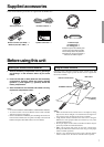
Supplied accessories
Check that the following accessories are supplied with the DTR-6.3/5.3.
AM loop antenna × 1
Remote controller (RC-481M) × 1
Batteries (AA, R6 or UM-3) × 2
FM indoor antenna × 1
321
30˚
30˚
Remote control sensor
STANDBY indicator
DTR-6.3/5.3
Approx. 16 feet
(5 meters)
Speaker cable label × 1
Front
Left
Front
Left
SP-B
/
Zone 2
Left
SP-B
/
Zone 2
Left
Surround
Right
Surround
Right
Surround Back
Right
Surround Back
Right
Zone 2
Right
Zone 2
Right
Front
Left
Front
Left
SP-B
/
Zone 2
Left
SP-B
/
Zone 2
Left
Front
Right
Front
Right
SP-B
/
Zone 2
Right
SP-B
/
Zone 2
Right
Front
Right
Front
Right
SP-B
/
Zone 2
Right
SP-B
/
Zone 2
Right
Surround
Right
Surround
Right
Center
Center
Center
Center
Surround
Left
Surround
Left
Surround
Left
Surround
Left
Surround Back
Right
Surround Back
Right
Zone 2
Right
Zone 2
Right
Surround Back
Left
Surround Back
Left
Zone 2
Left
Zone 2
Left
Surround Back
Left
Surround Back
Left
Zone 2
Left
Zone 2
Left
1
2
3
Speaker Cable
Power cord × 1
Protective caps
For digital jack × 1
For analog jack × 1
Protective caps for the Video4 jacks
on the front of the DTR-6.3/5.3. Be
sure to always attach the protective
caps when you are not connecting a
device to the VIDEO 4 jacks.