


27
Connections (DTR-5.3)
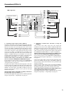
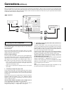
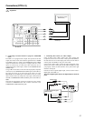
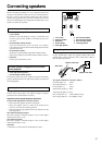
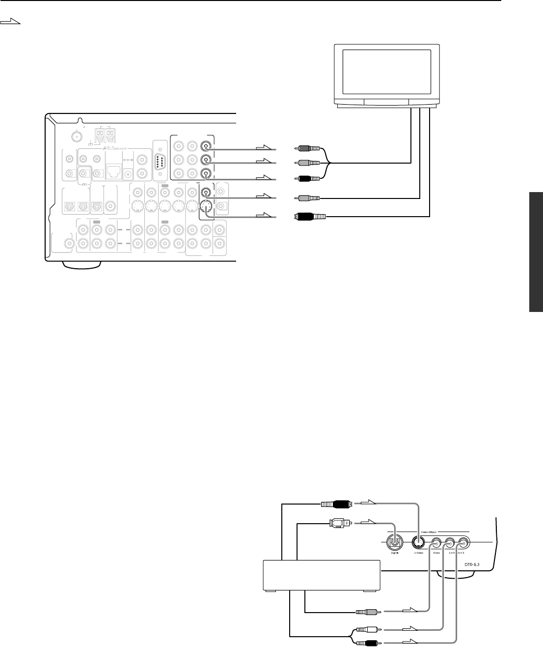
6. Connecting a television monitor or projector (MONITOR
OUT)
The DTR-5.3 is equipped with a simple Y/C separate circuit and
simple Y/C mixed circuit. Since both the signal from the S VIDEO
and VIDEO inputs are output to the MONITOR OUT S VIDEO
output, if the television or projector is equipped with an S video
input, it is unnecessary to connect the video connectors. If it is
equipped with only a video input, connect it to the MONITOR OUT
VIDEO output.
Using an RCA video cable, connect the video input jack (composite)
of the device to the MONITOR OUT VIDEO jack of the DTR-5.3.
Or if the device has an S video input jack, connect it to the
MONITOR OUT S VIDEO jack of the DTR-5.3 using an S video
cable. Or if the device has component video inputs, connect them to
the bank of COMPONENT VIDEO OUTPUT jacks on the DTR-5.3.
Note:
Note that the Setup Menu will only be displayed on the monitor
connected to MONITOR OUT and not those connected to the
COMPONENT VIDEO OUTPUT jacks.
Video output
Analog output
Right (red)
Left (white)
Digital output
(optical)
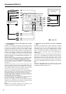
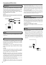
7. Video camera/Video game
(Video 4 Input)
S Video output
7. Connecting video camera, etc. (Video 4 Input)
Using an RCA video cable, connect the video output jack
(composite) of the device to the Video 4 Video jack of the DTR-5.3.
Or if the device has an S video output jack, connect it to the Video 4
S Video jack of the DTR-5.3 using an S video cable.
Using an RCA audio cable, connect the audio output jack of the
device to the Video 4 Audio jacks of the DTR-5.3. Make sure that
you properly connect the left channel to the L jack and the right
channel to the R jack.
If the device has an optical digital output, connect it to the Video 4
Digital jack of the DTR-5.3.
The Video 4 digital input is fixed to the Optical input on the front
panel.
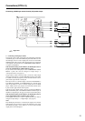
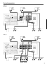
IR OUT
56K
40K
L
REMOTE
CONTROL
ANTENNA
FM
75
COAXIAL
OPTICAL
1
2
IN
IN
IN
IN
FRONT
SURR
CENTER
SUB
WOOFER
VIDEO 2
VIDEO 1
OUT
DIGITAL INPUT
DVD
MONITOR
OUT
DVD
TAPE
CD
SUBWOOFER
PRE OUT
L
R
R
VIDEO 3
VIDEO 2
VIDEO 3
VIDEO 1
OPTICAL
ININ
DIGITAL
OUTPUT
IN
INPUT 1
INPUT 2
OUTPUT
COMPONENT VIDEO
P
R
P
B
Y
OUT
OUT
DIGITAL
INPUT
L
R
AM
ZONE 2
OUT
DC IN
24V 1A
IR
OUT
IN
V
S
12 V
TRIGGER
OUT
LINE IN
RS232
L
R
IN
IN
A
B
A
B
V
S
6. TV monitor or projector
(MONITOR OUT)
Component video input
S Video input
Video input
P
R
P
B
Y
: Signal flow