


13
If the device has a digital output jack as well, be sure to also connect
it to either a DIGITAL INPUT (COAXIAL) or DIGITAL INPUT
(OPTICAL) jack on the DTR-5.2 depending on the type of
connector on the device.
With the initial settings of the DTR-5.2, the VIDEO 1 input
source is set for digital input at the COAXIAL 2 jack.
If the digital connection is made at a different jack, this must be changed
at the setup menu: Input Setup → Audio Setup → Digital Input (see
page 29).
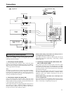
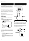
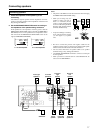
6. Connecting a satellite tuner, television, or settop box
(VIDEO 2/3)
If the device is equipped with an S video output terminal, connect it
to the S VIDEO 3 IN terminal with an S video cable. If it does not
have an S video output terminal, connect its video output terminal to
the VIDEO 3 IN terminal using an RCA-type video connection
cable. You do not need to connect to both the S VIDEO 3 IN and
VIDEO 3 IN terminals.
Using an RCA-type audio connection cable, connect the audio
output terminal on the satellite tuner or television to the same
VIDEO 3 IN audio jack on the DTR-5.2. Make sure that you
properly connect the left channel to the L jack and the right channel
to the R jack.
If the device have a digital output jack as well, be sure to also
connect it to either a DIGITAL INPUT (COAXIAL) or DIGITAL
INPUT (OPTICAL) jack on the DTR-5.2 depending on the type of
connector on the device.
With the initial settings of the DTR-5.2, the VIDEO 3 input
source is set for digital input at the OPTICAL 2 jack.
If the digital connection is made at a jack different from the initial
settings, this must be changed at the setup menu: Input Setup →
Audio Setup → Digital Input (see page 29).
You can also connect the device to the VIDEO 2 IN input jacks on
the DTR-5.2 just like you can to the VIDEO 3 IN input jacks.
With the initial settings of the DTR-5.2, the VIDEO 2 input
source is set for no digital input.
If you connect the device to the DIGITAL Input terminal, then this
input source must be set for digital input at the setup menu: Input
Setup → Audio Setup → Digital Input (see page 29).
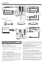
7. Connecting a television monitor or projector
(MONITOR OUT)
If the monitor or projector is equipped with an S video output
terminal, connect it to the MONITOR OUT S VIDEO terminal with
an S video cable. If it does not have an S video output terminal,
connect its video output terminal to the MONITOR OUT VIDEO
terminal using an RCA-type video connection cable. You do not
need to connect to both the MONITOR OUT S VIDEO and
MONITOR OUT VIDEO terminals.
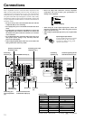
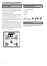
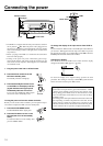
Connections
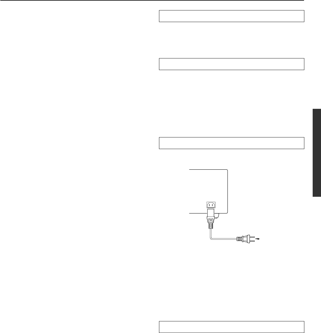
Power cord
(supplied)
To an AC
wall outlet
AC INLET
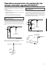
RS 232
The RS 232 port is to be used in conjunction with an external
controller to control the operation of the DTR-5.2 by using an
external device.
IR IN/OUT
If the DTR-5.2 is located inside a rack or cabinet that will not allow
infrared beams to reach the IR sensor, you will need to connect a
remote sensor to IR IN input to be able to use the remote controller.
Then install the remote sensor in an unblocked location where you
can easily point the remote controller.
Using a mini-jack connector, connect the IR emitter to the IR OUT
terminal on the DTR-5.2 and then place the IR emitter on the remote
sensor of the component or facing it.
AC INLET
Plug the supplied power cord into this AC INLET and then into the
power outlet on the wall.
• Do not use a power cord other than the one supplied with the
DTR-5.2. The power cord supplied is designed for use with the
DTR-5.2 and should not be used with any other adevice.
• Never have the power cord disconnected from the DTR-5.2
while the other end is plugged into the wall outlet. Doing so
may cause an electric shock. Always connect by plugging into
the wall outlet last and disconnect by unplugging from the wall
outlet first.
12V TRIGGER terminal
This terminal is provided so that you can use the operation of the
DTR-5.2 control the operation of another externally connected
device. Connect the component to this 1/8-inch mini-jack terminal
and when the set input source is selected, the device will turn on. Set
the 12V TRIGGER terminal using the 12V Trigger setting of the
Input Setup [31].