12
Connections
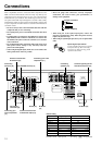
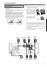
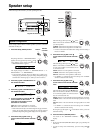
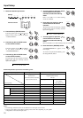
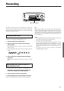
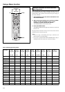
Connecting your video components
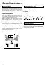
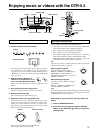
Below is an example of how you can connect your video
components to the DTR-5.2. Refer to the diagram above for the
following connection examples.
The flow of the video signals is as follows:
• The signal that comes in from VIDEO IN is sent to VIDEO
OUT.
• The signal that comes in from S VIDEO IN is sent to S VIDEO
OUT
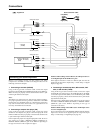
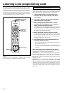
4. Connecting a DVD player (DVD)
If the device is equipped with an S video output terminal, connect it
to the DVD S VIDEO IN terminal with an S video cable. If it does
not have an S video output terminal, connect its video output
terminal to the DVD VIDEO IN terminal using an RCA-type video
connection cable. You do not need to connect to both the DVD S
VIDEO IN and DVD VIDEO IN terminals.
Using an RCA-type audio connection cable, connect the audio
output terminal on the device to the audio DVD IN jacks on the
DTR-5.2. Make sure that you properly connect the left channel to the
L jack and the right channel to the R jack.
If the device has a digital output jack as well, be sure to also connect
it to either a DIGITAL INPUT (COAXIAL) or DIGITAL INPUT
(OPTICAL) jack on the DTR-5.2 depending on the type of
connector on the DVD player.
With the initial settings of the DTR-5.2, the DVD input source is
set for digital input at the COAXIAL 1 jack.
If the digital connection is made at a different jack, this must be
changed at the setup menu: Input Setup → Audio Setup → Digital
Input (see page 29).
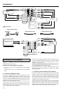
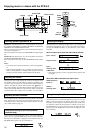
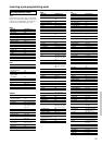
5. Connecting a video cassette recorder (VIDEO 1)
If the video cassette recorder is equipped with an S video output
terminal, connect it to the S VIDEO 1 IN terminal with an S video
cable. If it does not have an S video output terminal, connect its
video output terminal to the VIDEO 1 IN terminal using an RCA-
type video connection cable. You do not need to connect to both the
S VIDEO 1 IN and VIDEO 1 IN terminals.
Using an RCA-type audio connection cable, connect the audio
output terminal on the video cassette recorder to the same VIDEO 1
IN audio jacks on the DTR-5.2 and audio input terminal to the
VIDEO 1 OUT audio jacks. Make sure that you properly connect the
left channel to the L jack and the right channel to the R jack.
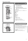
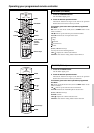
REMOTE
CONTROL
CENTER
SUB
WOOFER
FRONT
SURR
OPTICAL
COAXIAL
1
2
1 2
MULTI
CHANNEL INPUT
DIGITAL
INPUT
L
R
OUT
IN
TAPE
CD
RS
232
L
R
VIDE
IN
OUT
IN
IN
IN
S
VIDE
12
V
TRIGGER
MONITOR
OUT
DVD
VIDEO
3
VIDEO
2
VIDEO
1
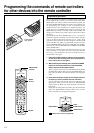
4. DVD player
(DVD)
Video output
S video output
Analog audio output
Digital audio output (Coaxial)
L (White)
R (Red)
5. VCR (VIDEO 1)
Video output
Video input
S video output
S video input
Analog audio output
Analog audio input
Digital audio output
(Coaxial)
L (White)
S video
V
R (Red)
L (White)
R (Red)
VIDEO
L
R
S
VIDEO
2
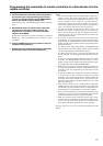
REMOTE
CONTROL
CENTER
SUB
WOOFER
FRONT
SURR
FER
OPTICAL
COAXIAL
1
2
12
T
MULTI
CHANNEL INPUT
DIGITAL
INPUT
L
R
OUT
IN
NO
TAPE
CD
RS
232
L
R
VID
IN
OUT
IN
IN
IN
S
VI
12
V
TRIGGER
MONITOR
OUT
DVD
VIDEO
3
VIDEO
2
VIDEO
1
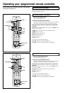
Digital audio output (optical)
Analog audio output
Video output
S video output
L (White)
R (Red)
6. Satelite tuner, TV,
or settop box
(VIDEO 2 / VIDEO 3)
Video input
S video input
7. TV monitor or Projector
(MONITOR OUT)
: Signal flow
Audio connection cable
L
R
Video connection cable S Video connection cableLeft (White)
Right (Red)