


10
Connections
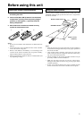
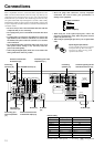
Here is explanation of how to connect the main components to the
DTR-5.2 in the standard manner. There are many ways that any one
component can be connected, and it is up to you to decide which
method best fits your situation. The directions given here are only
one option and should only be thought of as such. It is best to fully
understand the nature of each connector and terminal as well as each
of your components and their features to ascertain which method of
connection is best.
• Be sure to always refer to the instructions that came with the
component that you are connecting.
• Do not plug in the power cord until all connections have been
made.
• For input jacks, red connectors (marked R) are used for the
right channel, white connectors (marked L) are used for the
left channel, and yellow connectors (marked V) are used for
video connection.
• Do not bind audio/video connection cables with power cords
and speaker cables. Doing so may adversely affect the
picture and sound quality.
• When using the digital inputs, make sure to also connect the
analog connections whenever possible.
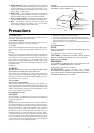
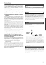
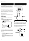
• Insert all plugs and connectors securely. Improper
connections can result in noise, poor performance, or
damage to the equipment.
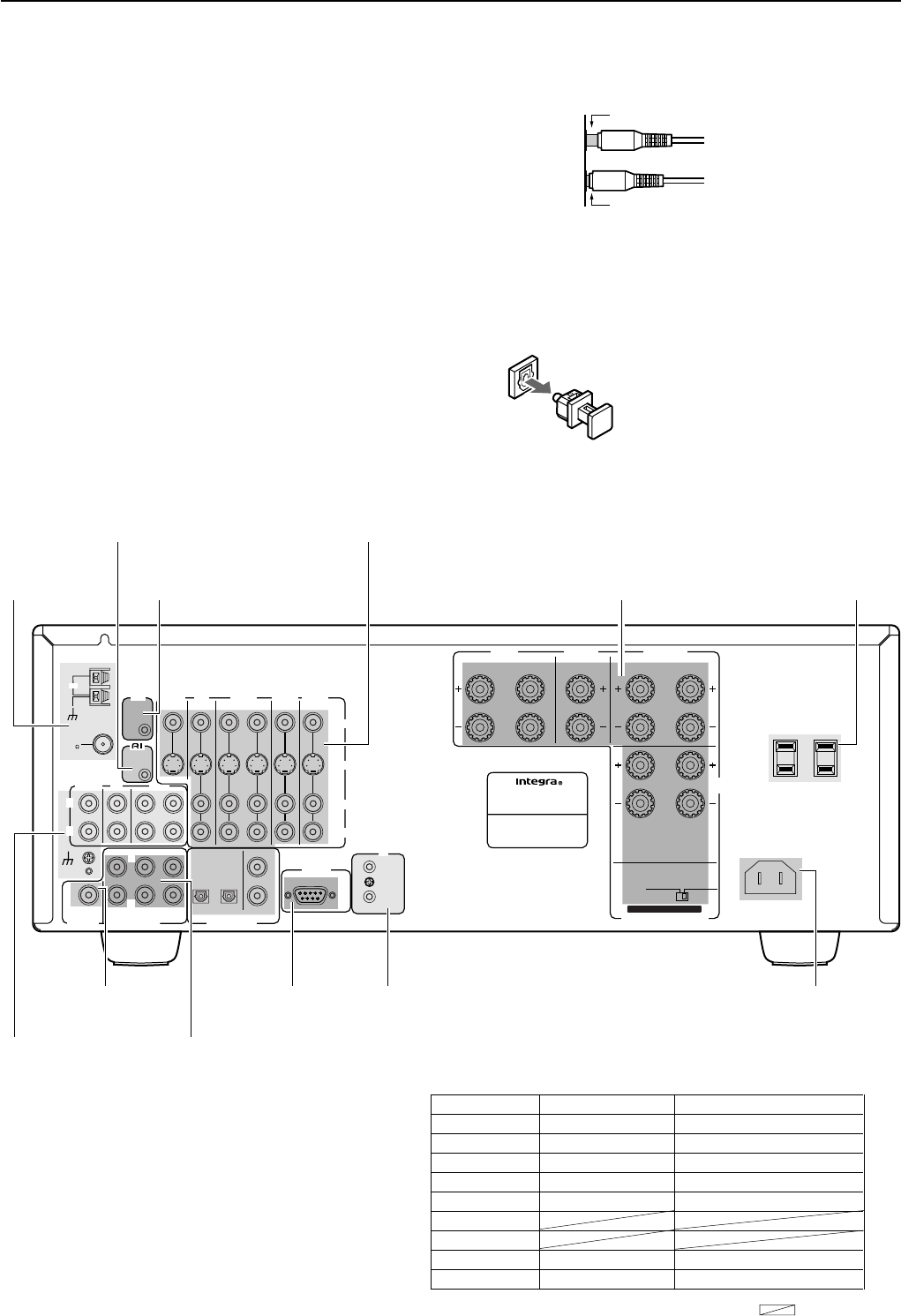
Improper connection
Inserted completely
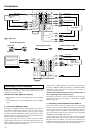
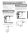
• When using one of the optical input jacks, remove the
protective cap and keep it safely. When the jack is not used,
replace the protective cap.
• When using an optical input jack, always use an optical fiber
cable.
Optical digital input terminal
An optical digital input terminal is equipped
with a protection cap. When connecting,
remove this cap. When not using, put the
cap back on the terminal.
6 OHMS
MIN.
/
SPEAKER
R
L
REMOTE
CONTROL
FM
75
AM
ANTENNA
GND
4 OHMS
MIN.
/
SPEAKER
CENTER
SPEAKER
SURROUND
SPEAKERS
R
L
R
L
R
L
L
R
CENTER
SUB
WOOFER
FRONT
SURR
SUBWOOFER
OPTICAL
COAXIAL
1
2
12
PRE OUT
MULTI
CHANNEL INPUT
DIGITAL
INPUT
L
R
OUT
IN
PHONO
TAPE
CD
IMPEDANCE SELECTOR
SET BEFORE POWER ON
RS 232
AC INLET
CAUTION
:
SEE INSTRUCTION MANUAL
FOR CORRECT SETTING.
AC OUTLETS
AC 120
V 60
Hz
SWITCHED
TOTAL 120
W 1
A
MAX.
FRONT
SPEAKERS
A
FRONT
SPEAKERS
B
L
R
VIDEO
IN
OUT
IN
IN
IN
IN
IR
AV RECEIVER
MODEL NO. DTR-5.2
S
VIDEO
OUT
12 V
TRIGGER
MONITOR
OUT
DVD
VIDEO
3
VIDEO
2
VIDEO
1
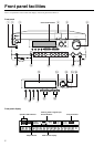
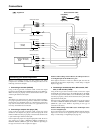
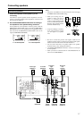
Connecting
antennas [19]
Connect to devices with
z terminals [14]
Connecting your video
components [11]
Cautions regarding the AC
OUTLETS connectors [14]
Connect to devices with
multichannel output [14]
Connecting a
subwoofer [16]
Connecting your
audio components
[11]
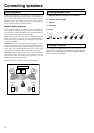
Connecting
speakers [16]
Default setting
Input source Digital input Multichannel
DVD COAX 1 YES
VIDEO 1 COAX 2 NO
VIDEO 2 ---- NO
VIDEO 3 OPT 2 NO
TAPE ---- NO
FM
AM
PHONO ---- NO
CD OPT 1 NO
COAX: Coaxial OPT: Optical ----: No setting : Not applicable
12V TRIGGER terminal [13]
RS 232 [13] AC INLET [13]
IR IN/OUT
[13]