


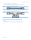

Wiringdigitalcommunications
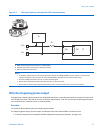
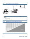
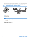
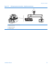
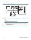
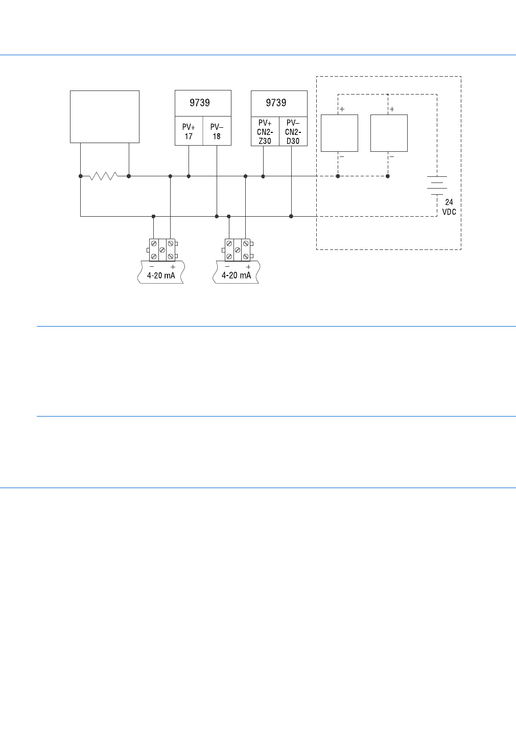
Figure 6-3 Wiring to a typical HART
®
network
PV+
17
PV–
18
PV+
CN2-
Z30
PV–
CN2-
D30
4-20 mA
4-20 mA
24
VDC
9739 9739
A
B
C
D
E
E
F
A HART communications tool, ProLink II, or AMS modem
B 250 Ω load
C IFT9701
D R-Series
E SMART FAMILY
®
transmitter
F DC source required for other HART 4–20 mA passive transmitters
Notes
• SMART FAMILY devices require a minimum loop resistance of 250 Ω. Loop resistance must not exceed 1000 Ω.
• Connect the mA output from each9739 MVD transmitter together so they terminate at a common load resistor, with at
least 250 Ω impedance, installed in series.
• For optimum HART communication, make sure the output loop is single-point grounded to instrument grade ground.
38MicroMotion9739MVDTransmitters