Wiringthe9739MVDtransmittertothesensor
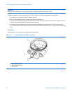
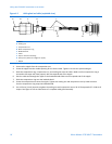
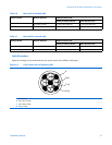
Figure 4-3 Cable gland and cable (exploded view)
A
B
C
D
E
F
G
H
I
A Cable
B Sealing nut
C Compression nut
D Brass compression ring
E Braided shield
F Cable
G Tape or heat-shrink tubing
H Clamp seat (shown as integral to nipple)
I Nipple
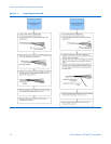
3. Unscrew the nipple from the compression nut.
4. Screw the nipple into the conduit opening for the 9-wire cable. Tighten it to one turn past hand-tight.
5. Slide the compression ring, compression nut, and sealing nut onto the cable. Make sure the compression ring is
oriented so the taper will mate properly with the tapered end of the nipple.
6. Pass the cable end through the nipple so the braided shield slides over the tapered end of the nipple.
7. Slide the compression ring over the braided shield.
8. Screw the compression nut onto the nipple. Tighten the sealing nut and compression nut by hand to ensure
that the compression ring traps the braided shield.
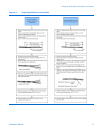
9. Use a 25-mm (1-inch) wrench to tighten the sealing nut and compression nut to 20–25 foot-pounds (27–34 N-m) of
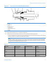
torque. See Figure 4-4 for an illustration of a complete cable gland assembly.
16MicroMotion9739MVDTransmitters


