


Chapter 5
Wiring the outputs
Topics covered in this chapter:
¨ Analog output terminals
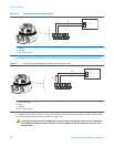
¨ Wire the primary and secondary mA outputs
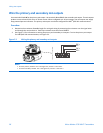
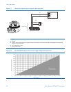
¨ Wire the frequency/pulse output
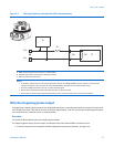
¨ Wire the discrete output
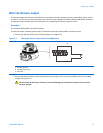
¨ Wire the discrete input
¨ Wire to a pressure transmitter
Analog output terminals
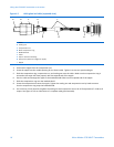
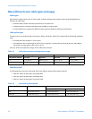
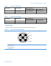
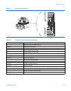
Use the upper and lower terminal blocks on the right side of the partition on the 9739 MVD transmitter electronics
module for analog output wiring connections. Use twisted-pair, shielded cable for all I/O connections. The partition on the
transmitter electronics module keeps intrinsically safe wiring to the sensor separated from non-intrinsically safe analog
output wiring. You can unplug the terminal block connectors from the electronics module for easier installation of wiring.
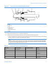
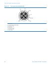
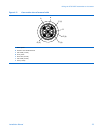
Figure 5-1 and Table 5-8 identify the analog output terminals and their functions for the 9739 MVD transmitter.
Analog output wiring is not intrinsically safe. Keep output wiring separated from power supply wiring and
intrinsically safe sensor wiring. Failure to comply with requirements for intrinsic safety in a hazardous area
could result in an explosion.
Important
The Service port clips on the user interface of the
9739 MVD transmitter are directly connected to RS-485 terminals
(26 and 27). If you wire the transmitter for RS-485 digital communications, you cannot use the Service port clips for
communication with the transmitter.
24MicroMotion9739MVDTransmitters